My WEDC
Gateway to managing your resources and events
Gateway to managing your resources and events
Water Engineering and Development Centre
Please note: You will need to log in to your My WEDC account to download graphics – please sign up here if you don't already have an account.
Below are the graphics for WEDC Graphics: Emergency water supply
Please click on the download link below your selected graphic to download it.
|
|

| ||
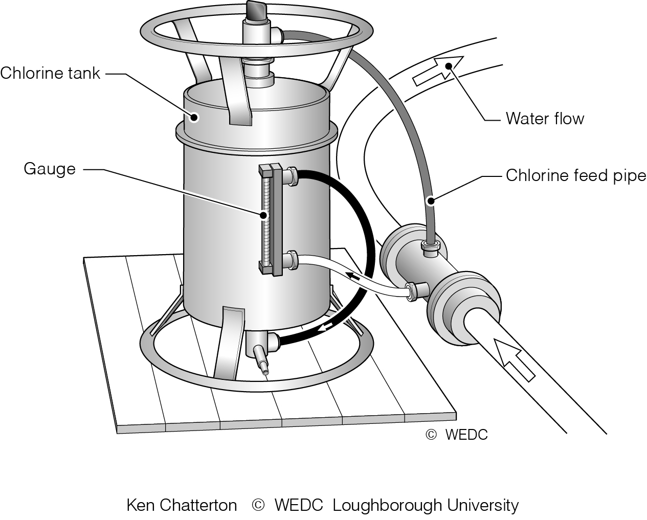
1-7 A chlorinator | 10-10 Pipeline profile from storage tank 2 | 10-11 Pipeline profile from junction 2 to standpost 2 | ||
|
|

| ||
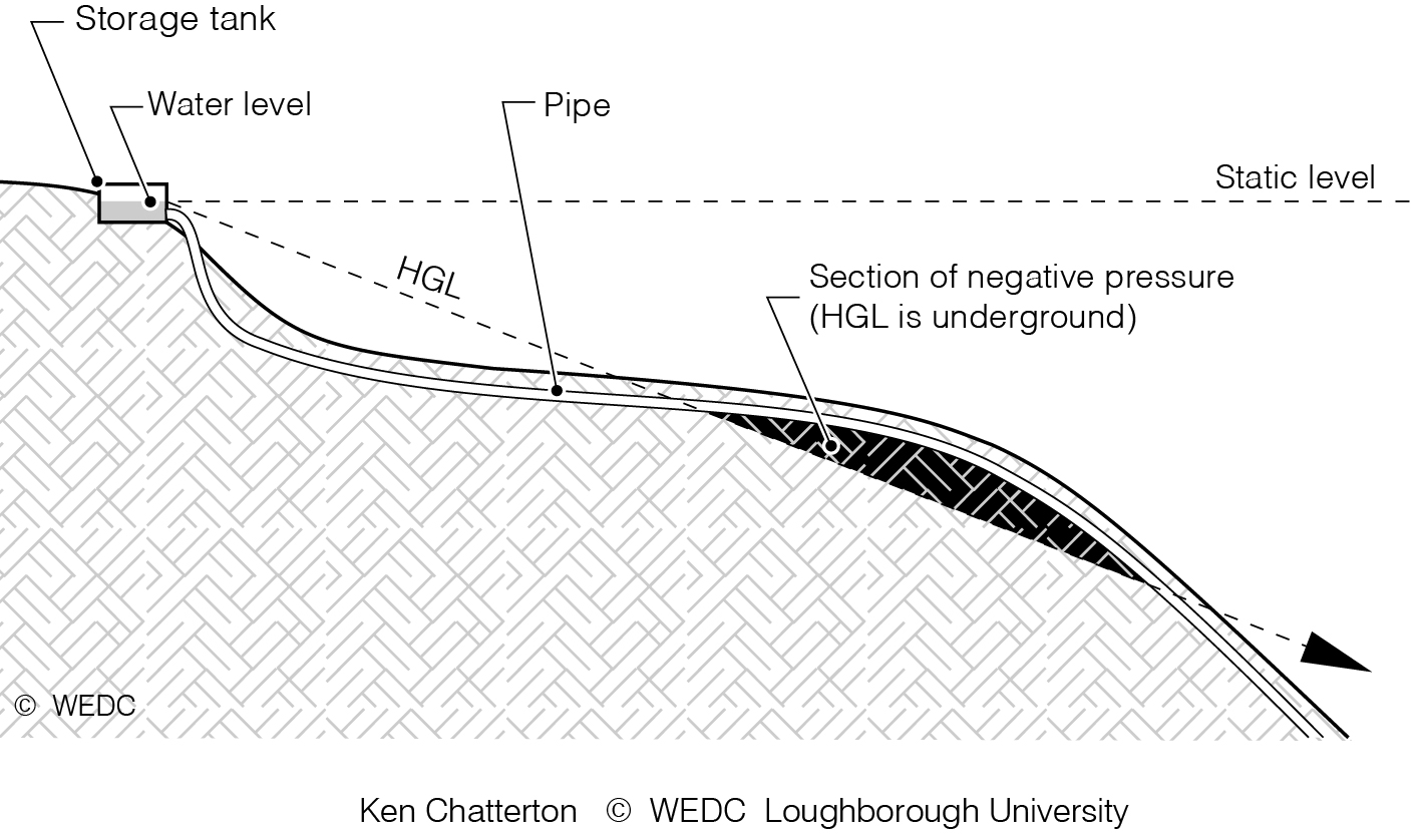
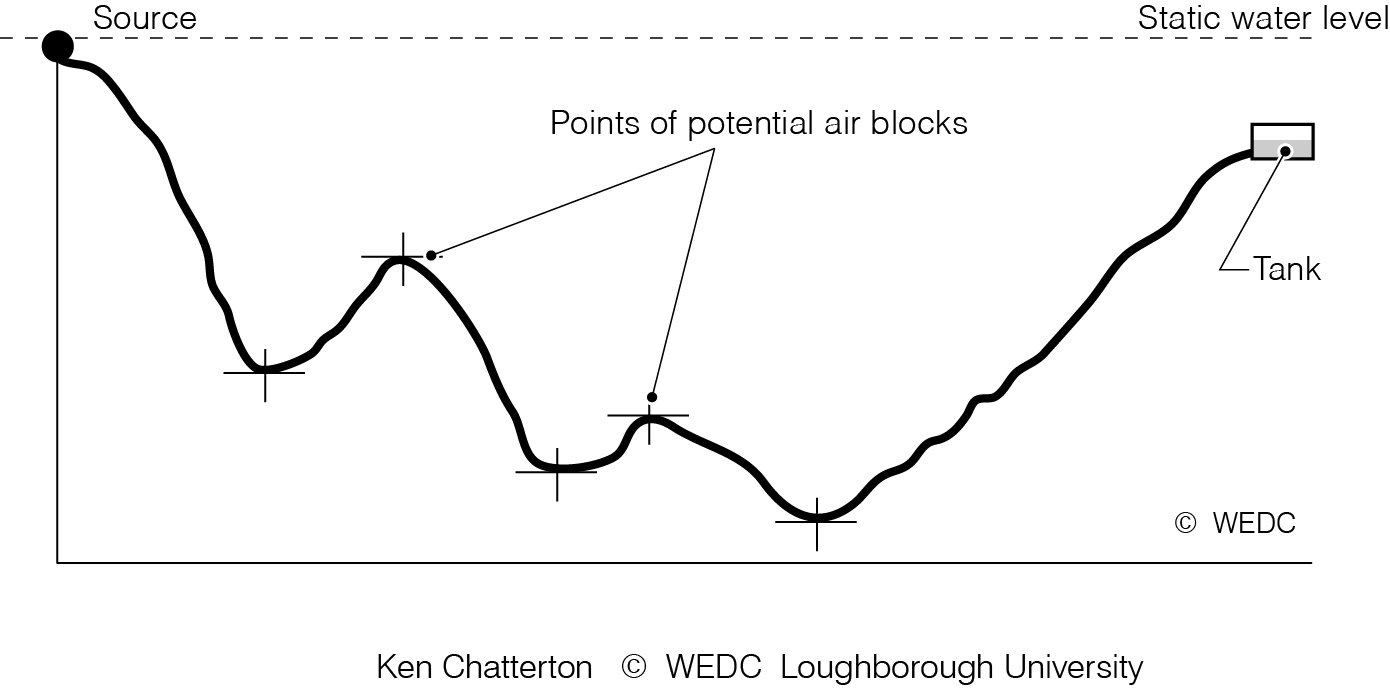
10-12 Negative pressure in pipeline caused by HGL dropping below level of pipe | 10-13 Points in pipeline where air might collect and restrict flow | 10-2 Effect of pipe flow on pressure energy | ||
|

|
| ||
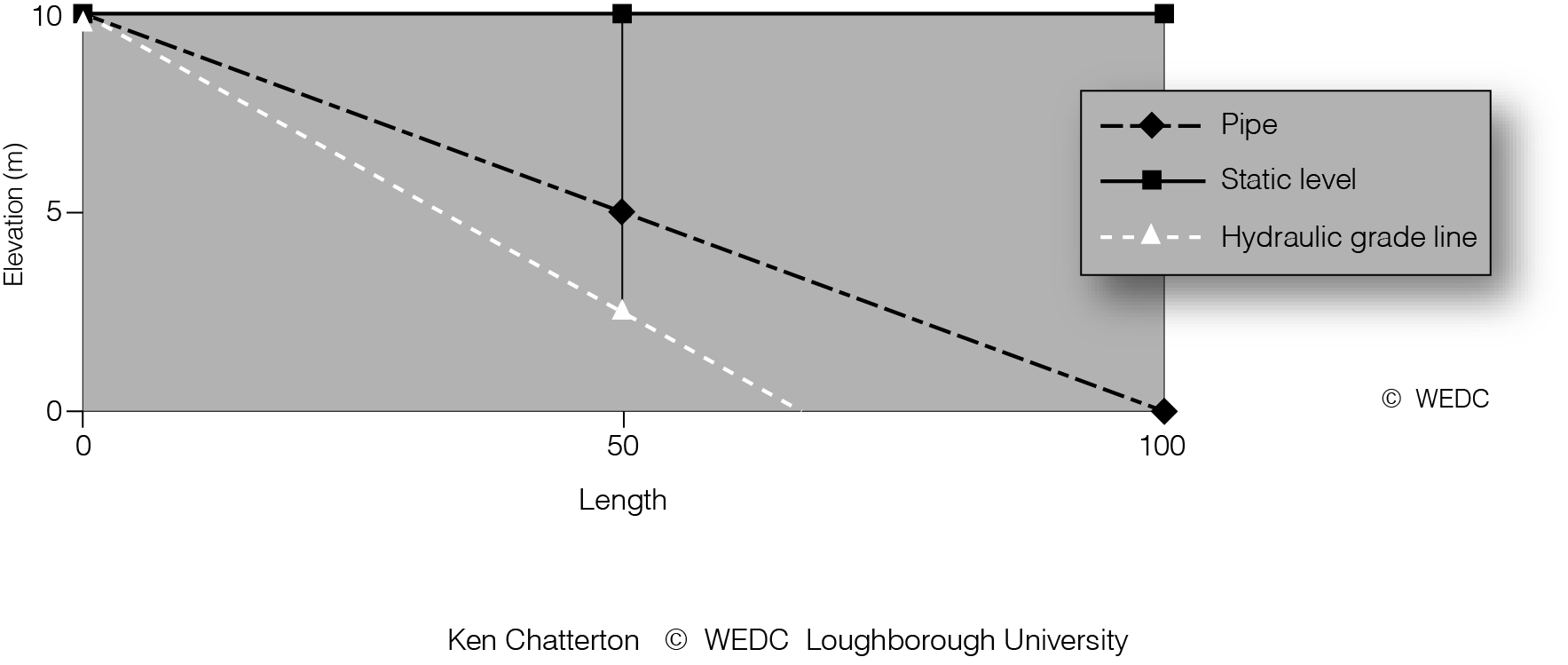
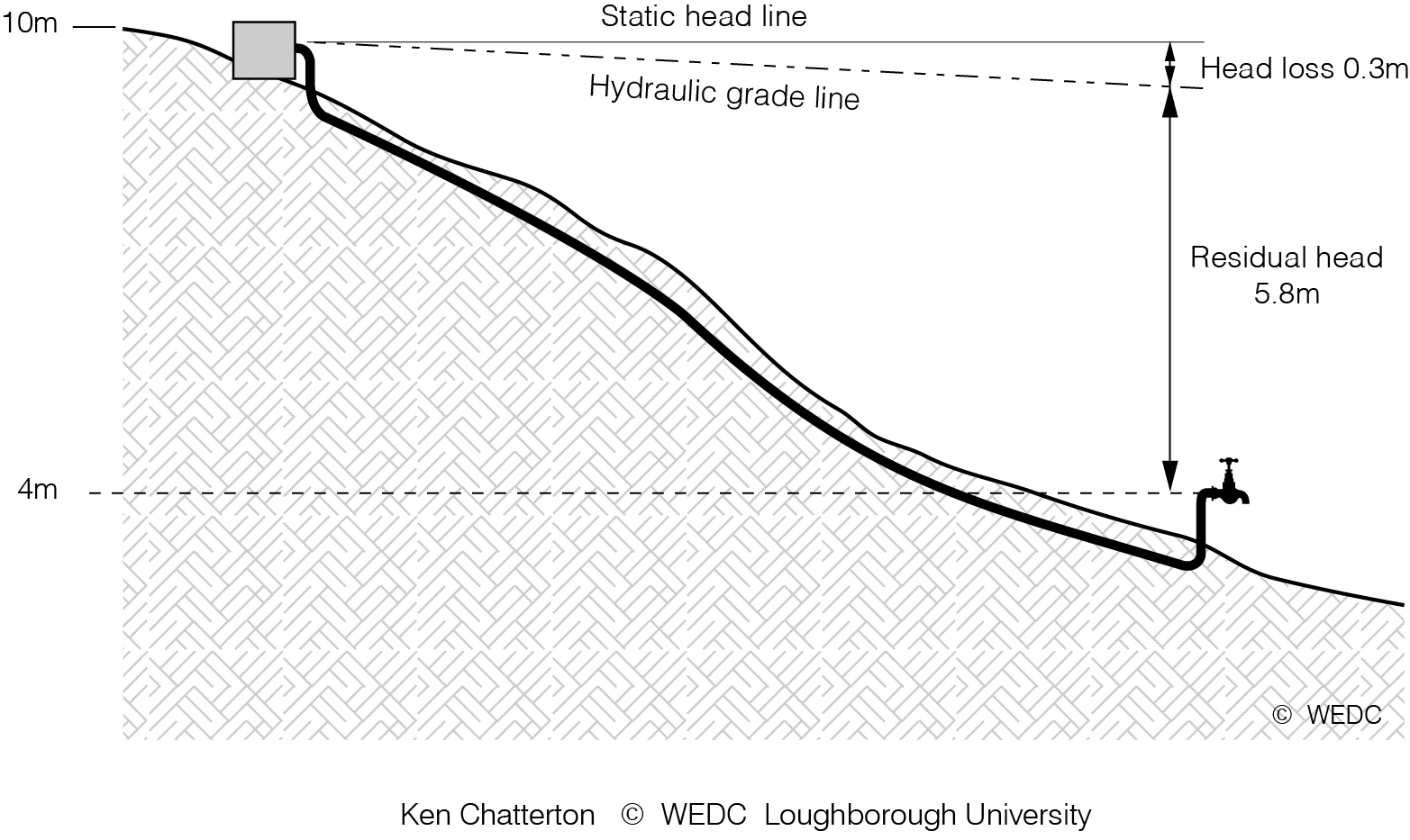
10-3 Schematic profile of hydraulic gradient line | 10-4 Elevation of pipeline between storage tank and tapstand | 10-6 Hydraulic gradient line for design example | ||
|
|
| ||
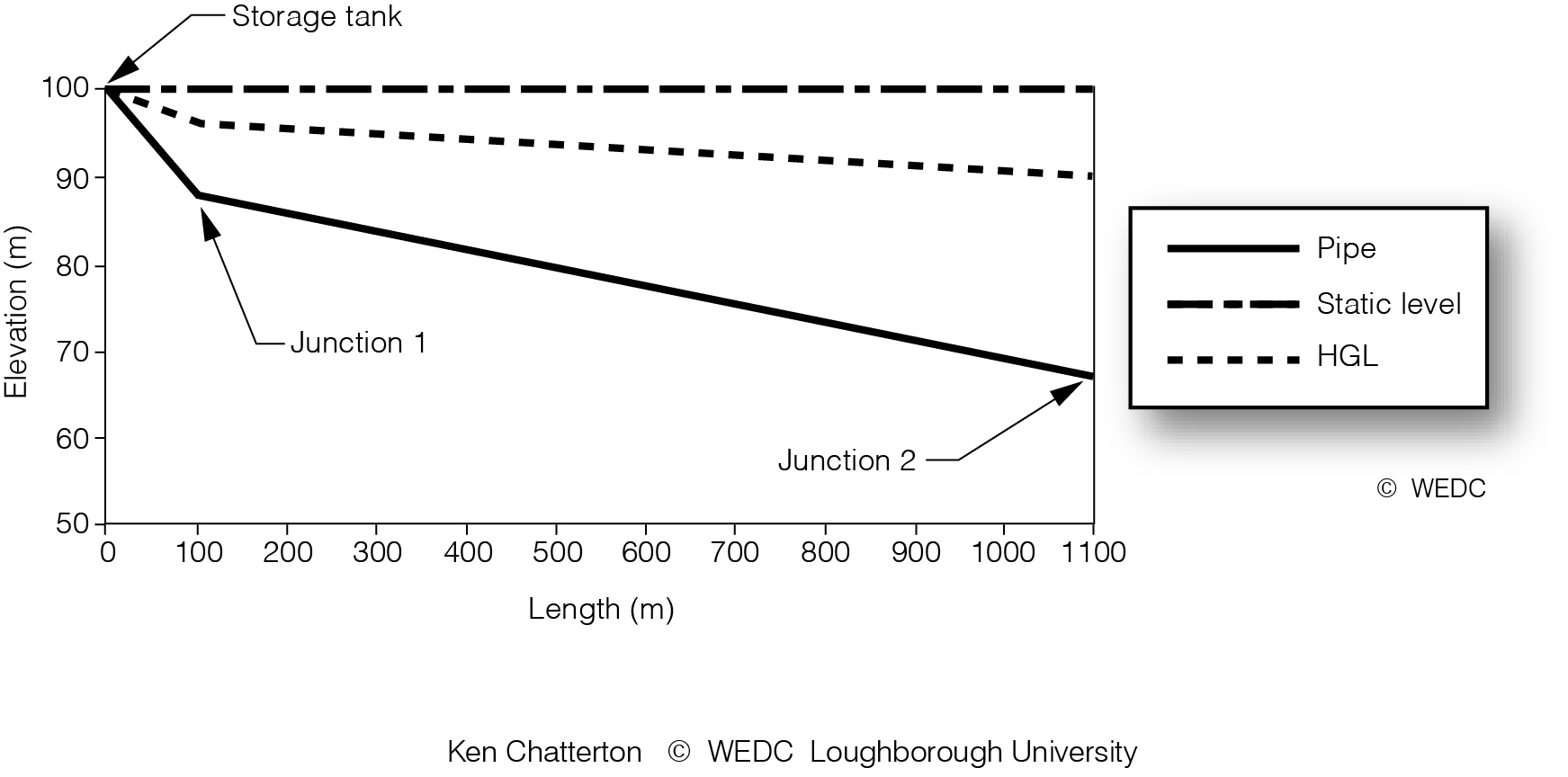
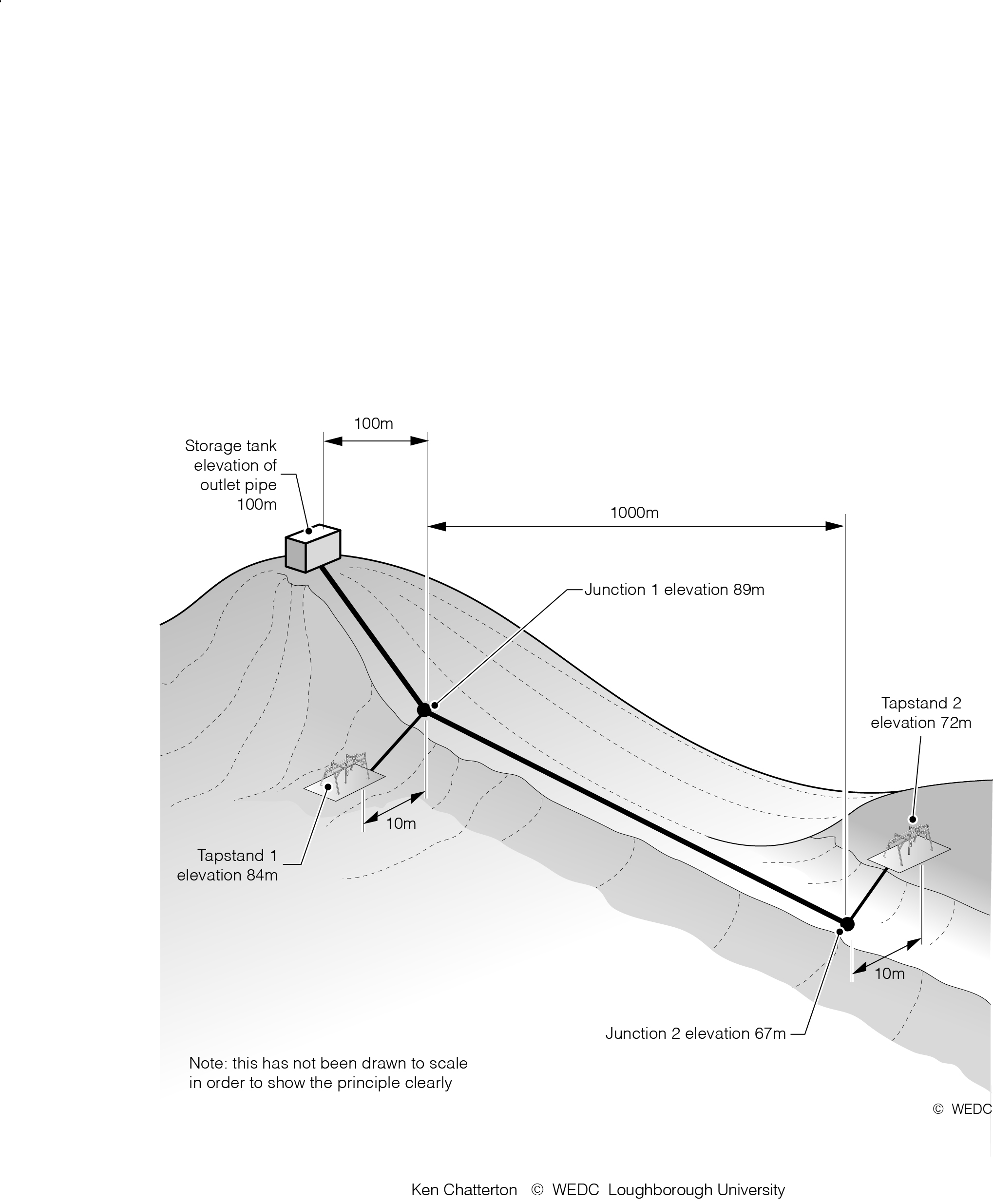
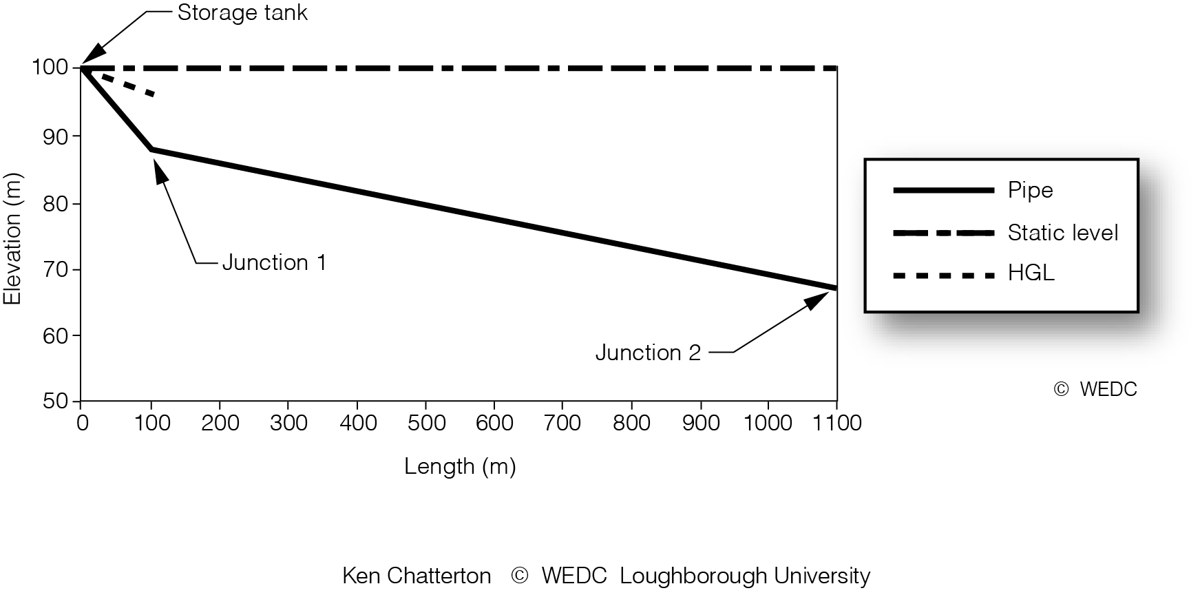
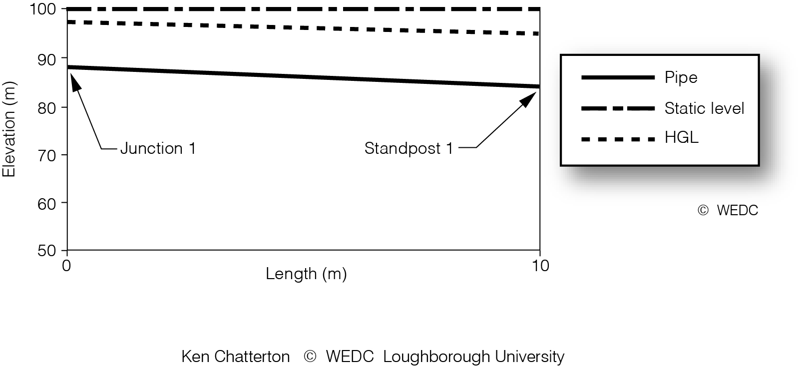
10-7 Layout of a small gravity flow distribution network | 10-8 Pipeline profile from storage tank | 10-9 Pipeline profile from junction 1 to standpost 1 | ||
|
|
| ||
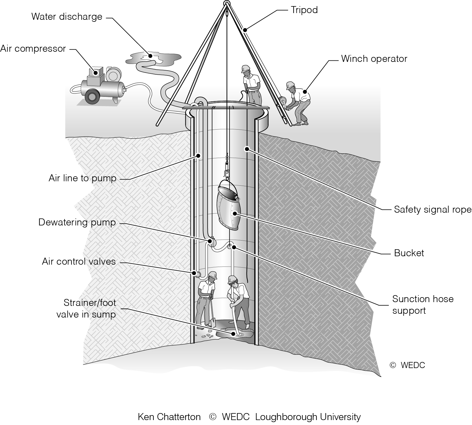
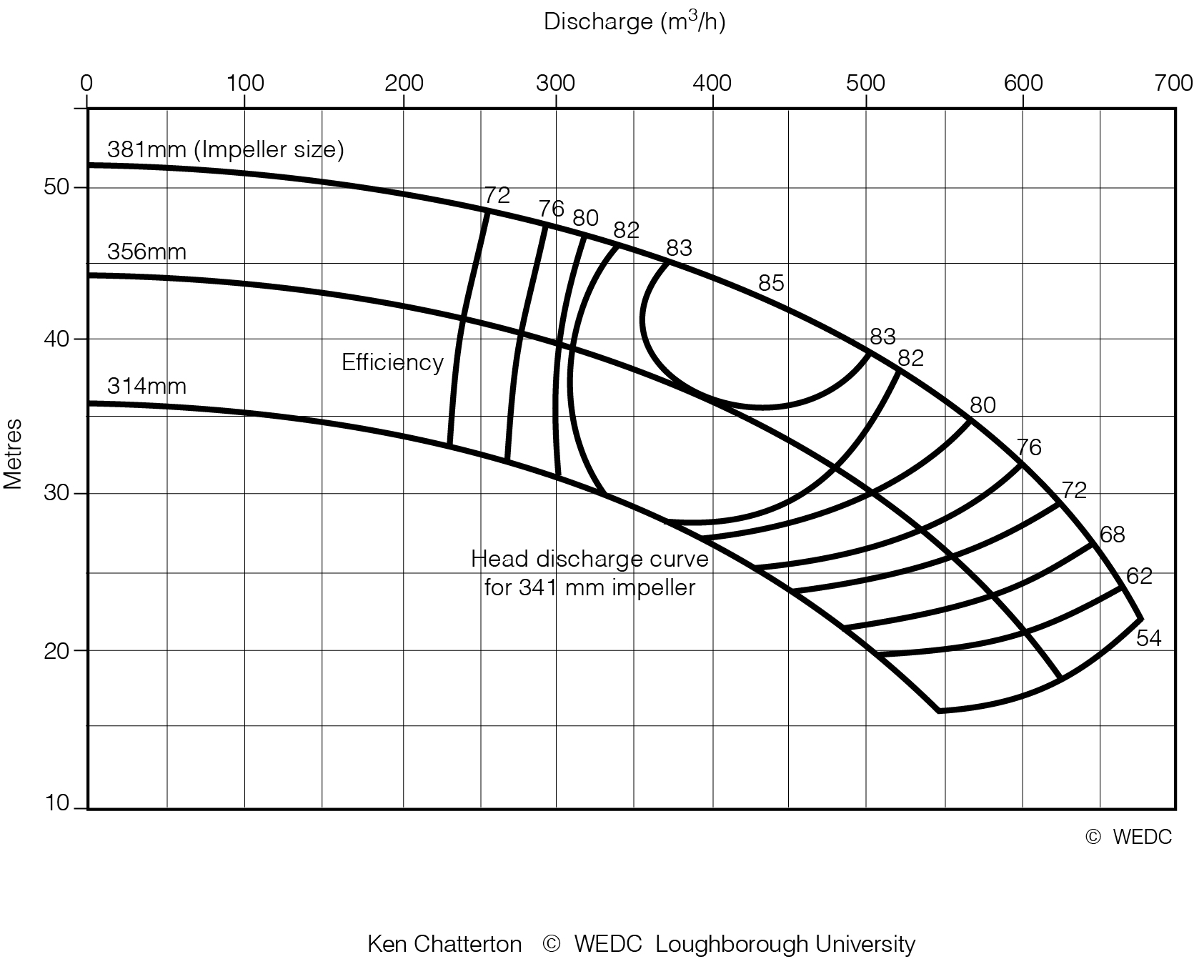
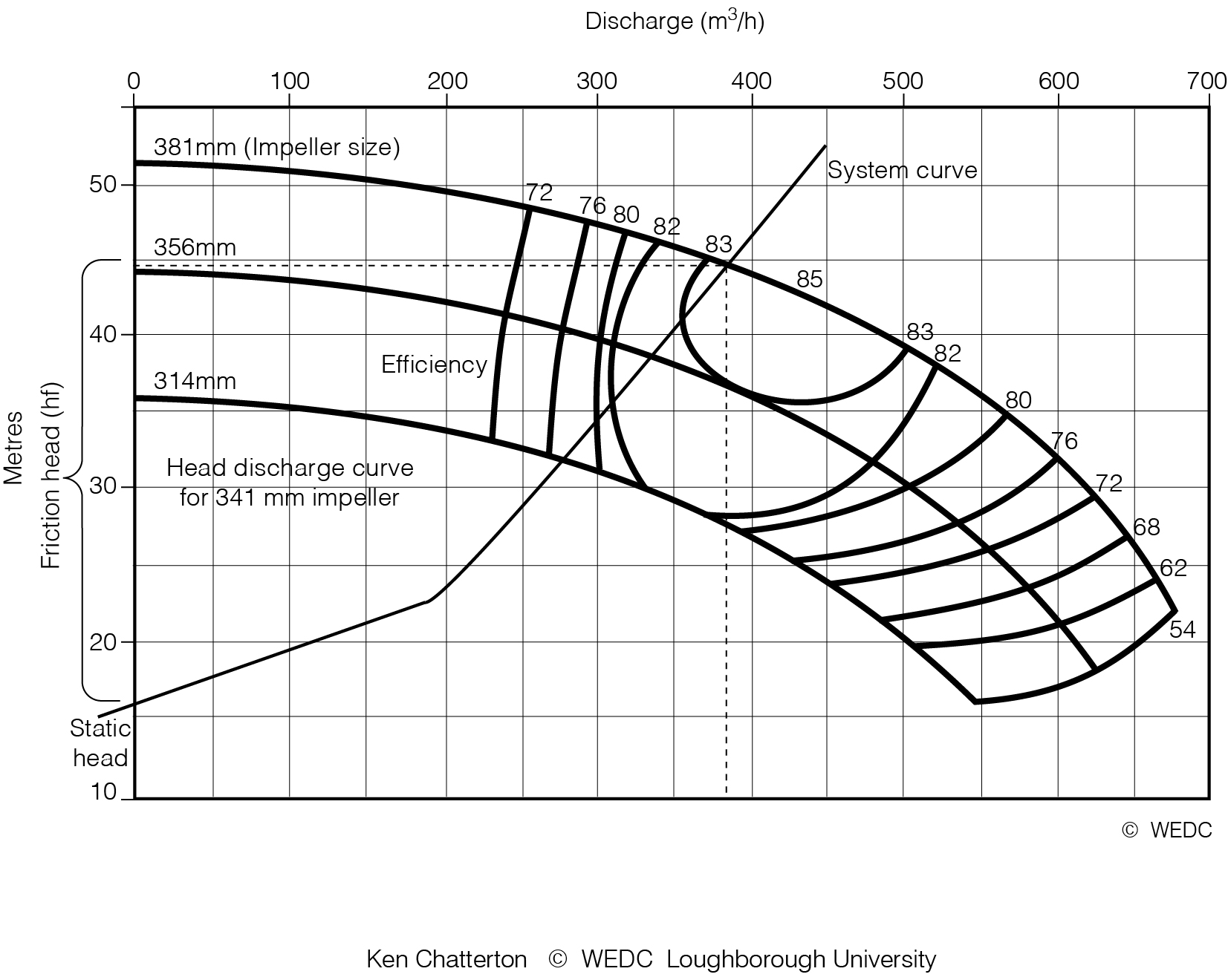
11-10 Digging a shallow well using compressed air to dewater | 11-11 Pump characteristics for large single impeller centrifugal pump | 11-12 Pipeline system curve | ||

|
|
| ||
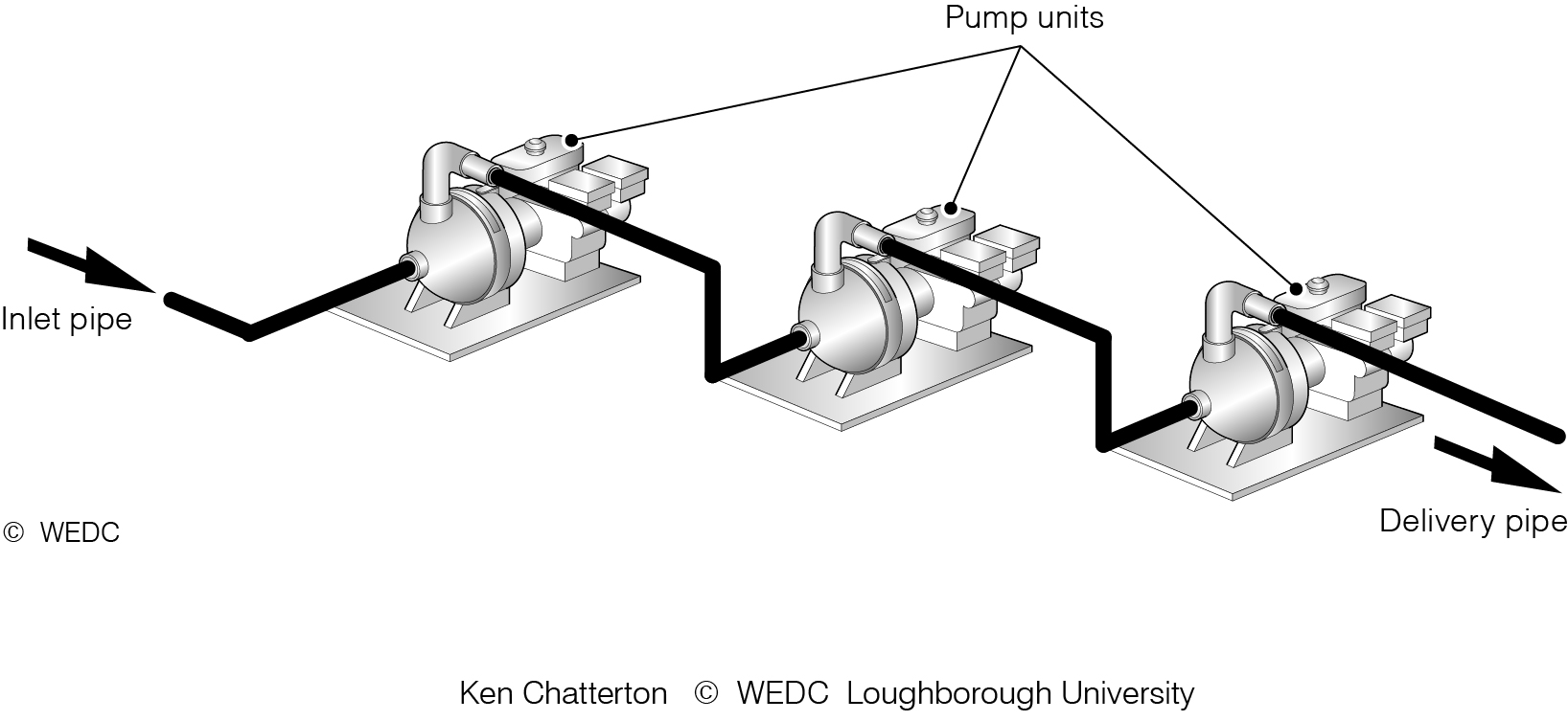
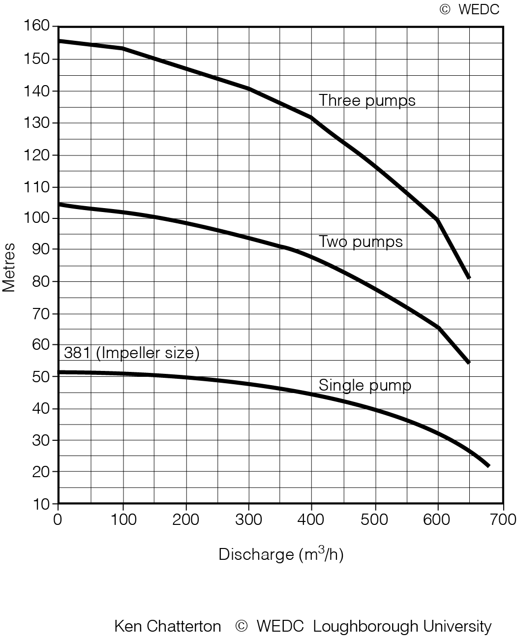
11-13 Comparison of head discharge curves for centrifugal and positive displacement pump | 11-14 Pumps connected together in a series | 11-15 Head discharge curves for three equal pumps connected | ||

|
|

| ||
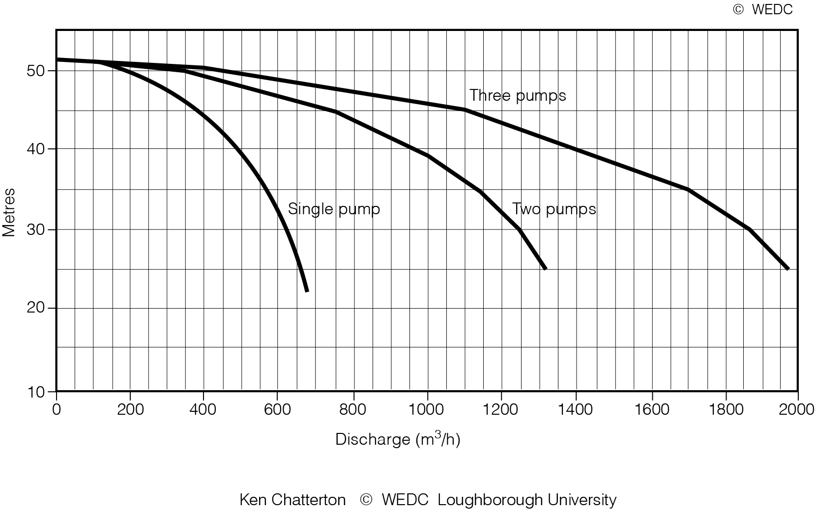
11-16 Pumps collected together in parallel | 11-17 Head discharge curves for three equal pumps connected | 11-1 Classification of pumps commonly used in emergency water supply | ||
|
|

| ||
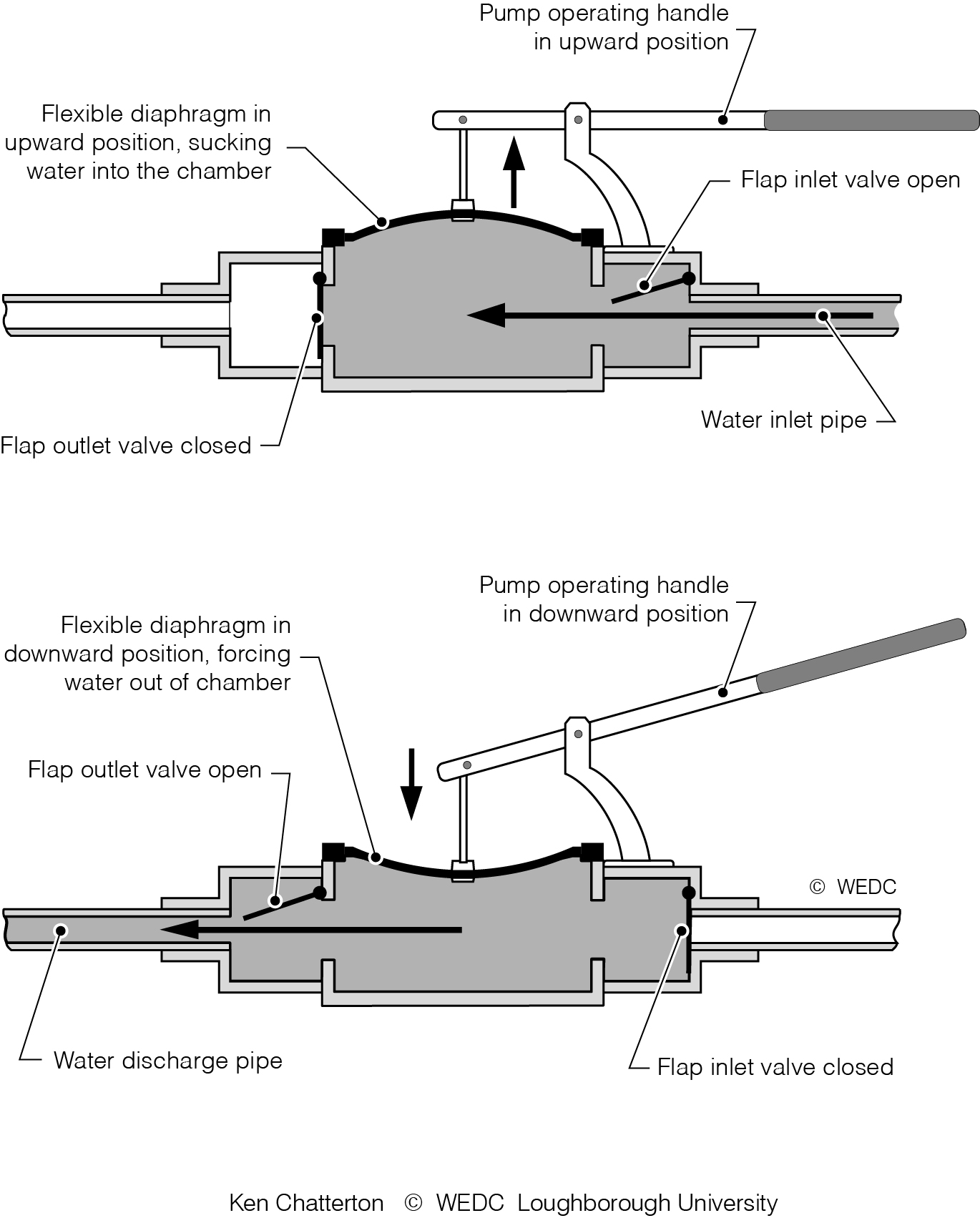
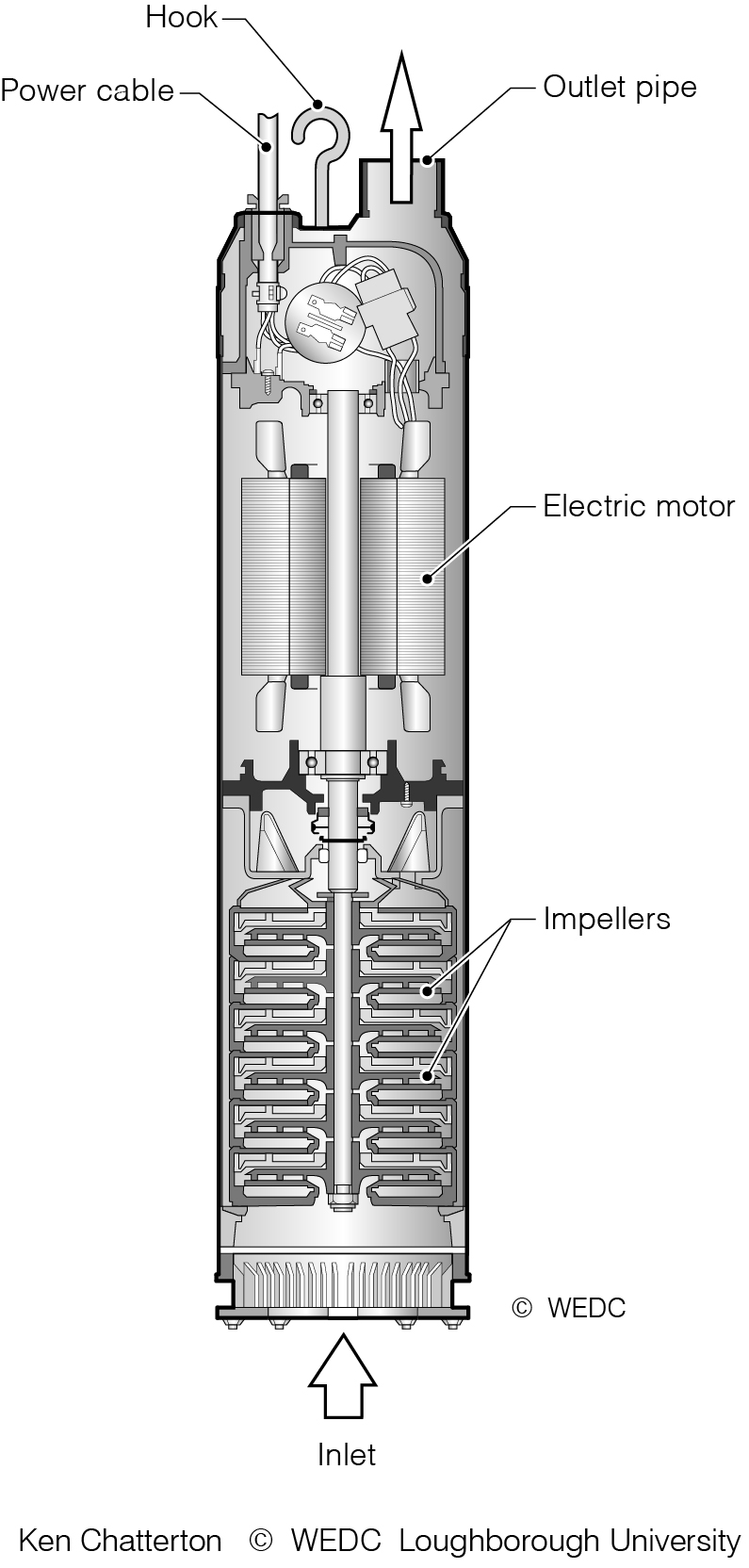
11-2 Diaphragm pump | 11-6 Multi-stage submersible pump | 11-7 Submersible electric pumps | ||
|
|
| ||
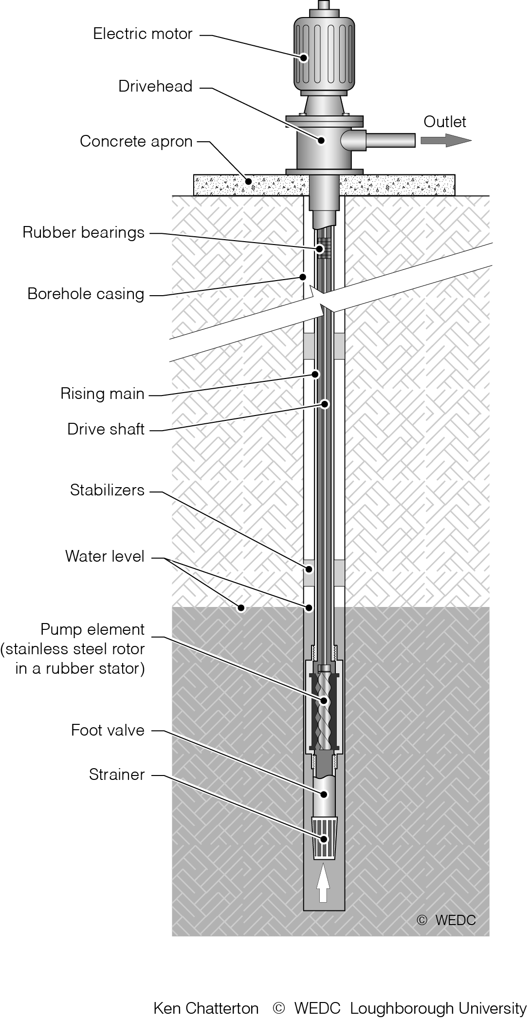
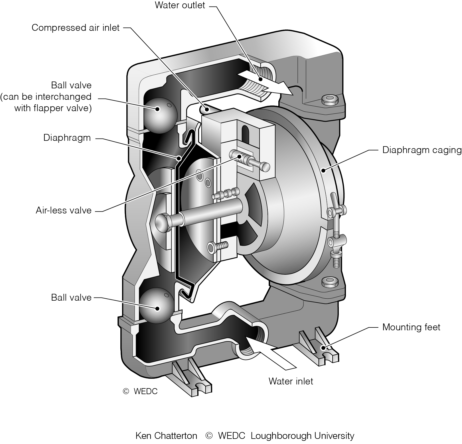
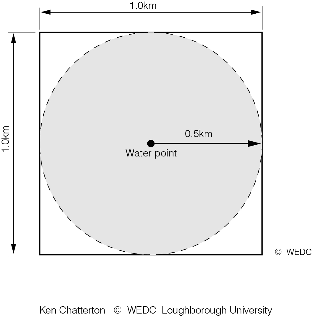
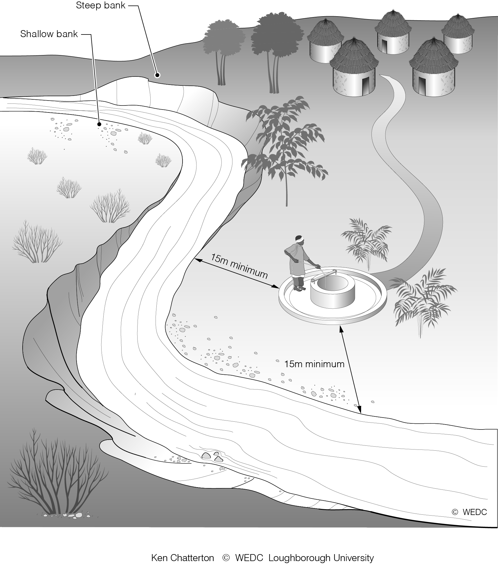
11-8 Progressive cavity pump mounted in borehole | 11-9 Compressed air operated diaphragm pump | 2-2 Maximum distance from household or water point | ||
|
|
| ||
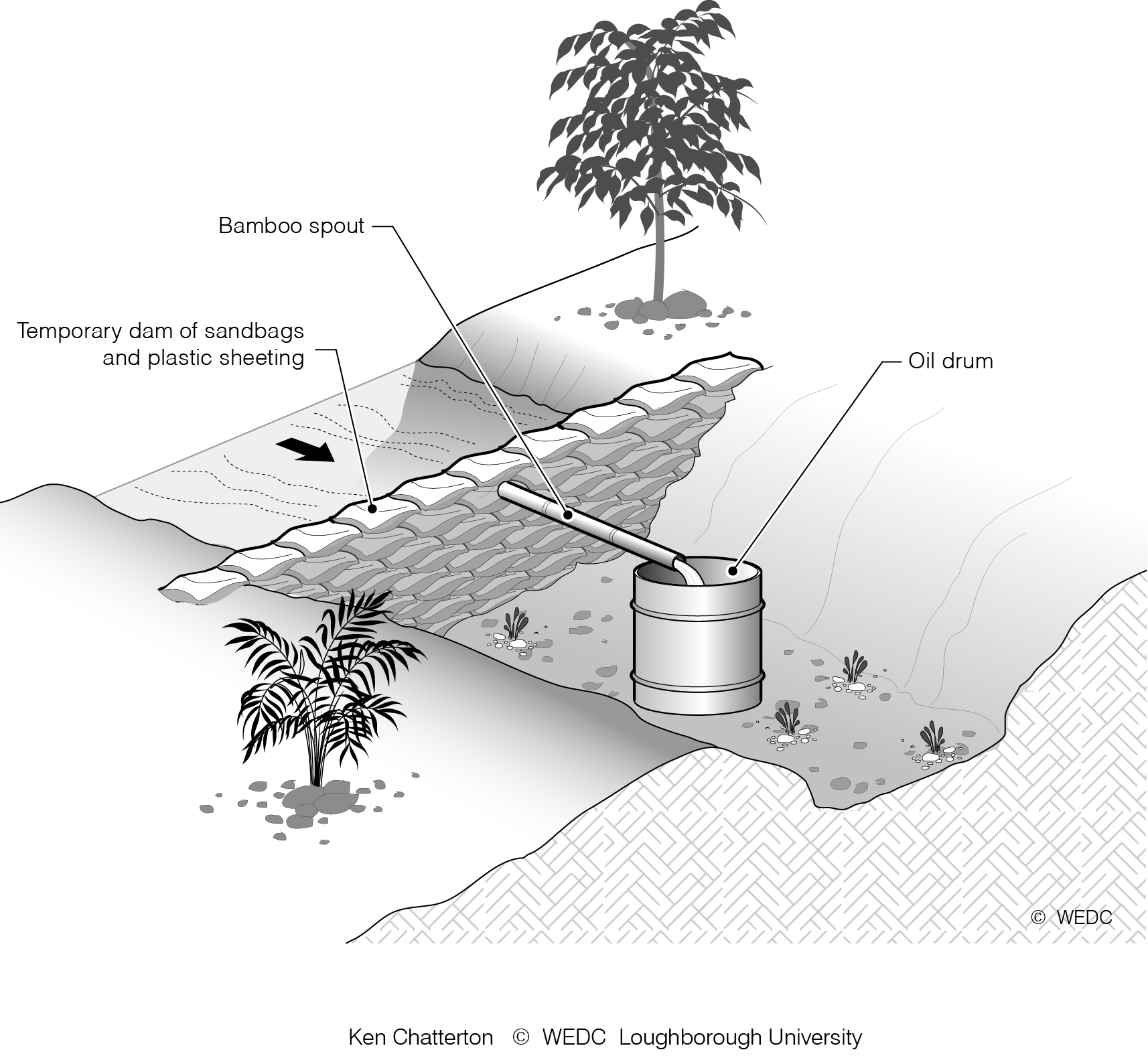
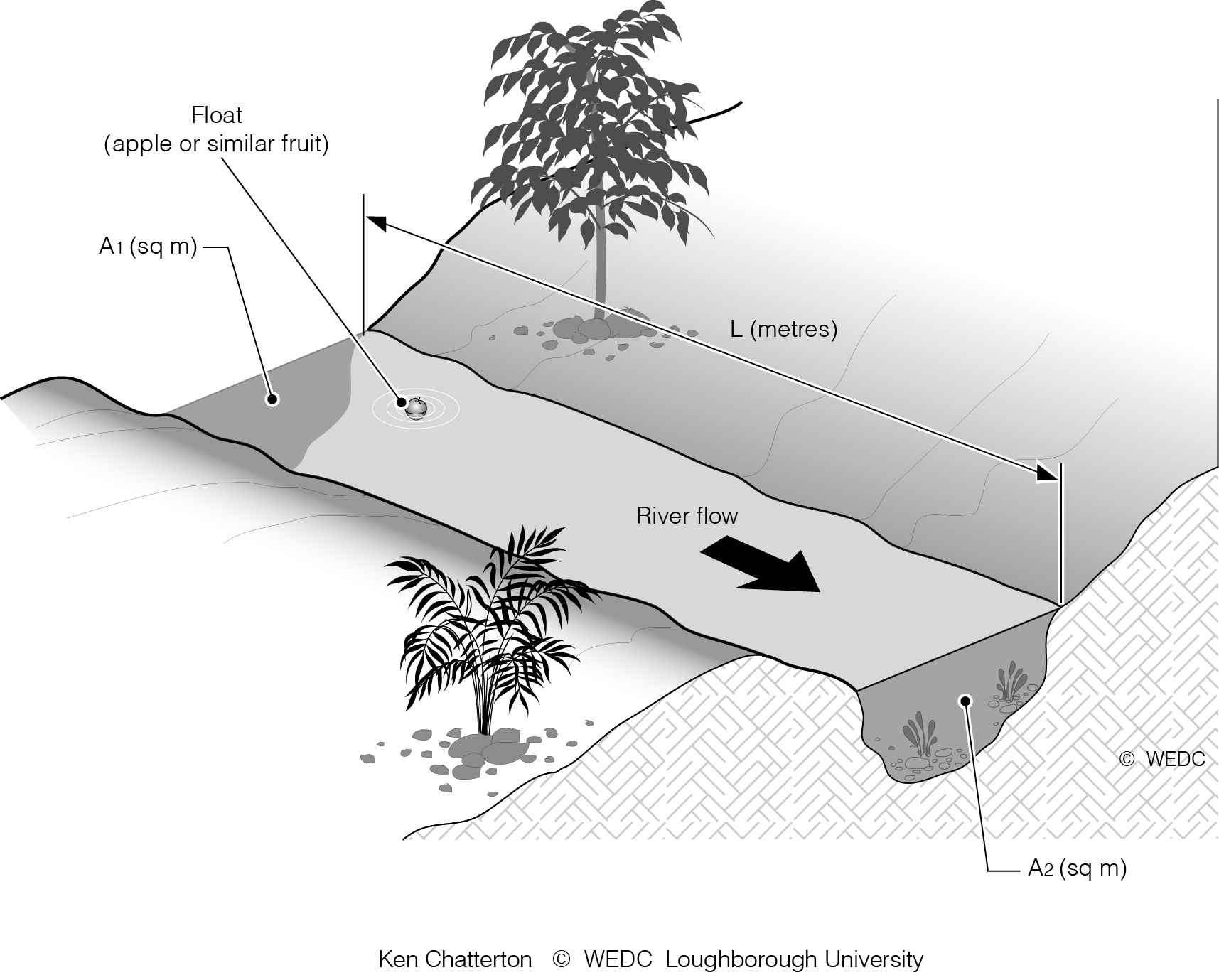
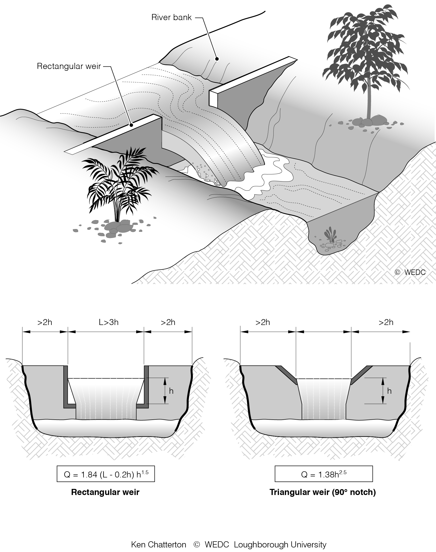
4-1 Flow measurement temporary dam | 4-2 Flow measurement | 4-3 Flow measurement - weirs | ||

|

|
| ||
4-5 Rock distribution | 4-6 Cross-sectional representation of a weathered crystalline rock aquifer | 4-7 Drill pipe | ||
|
|
| ||
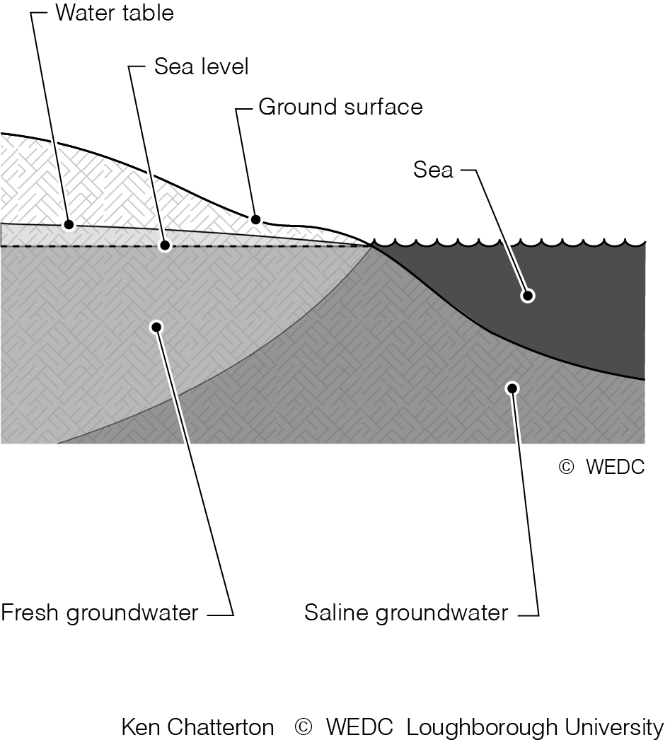
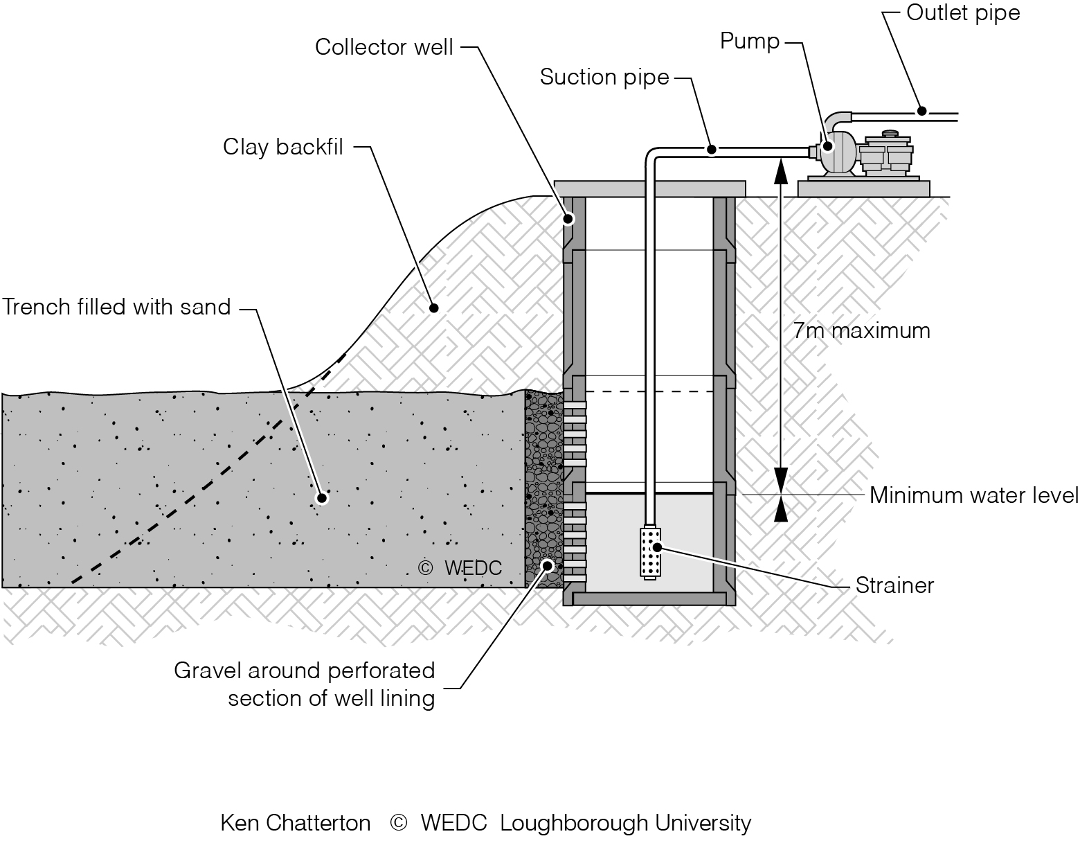
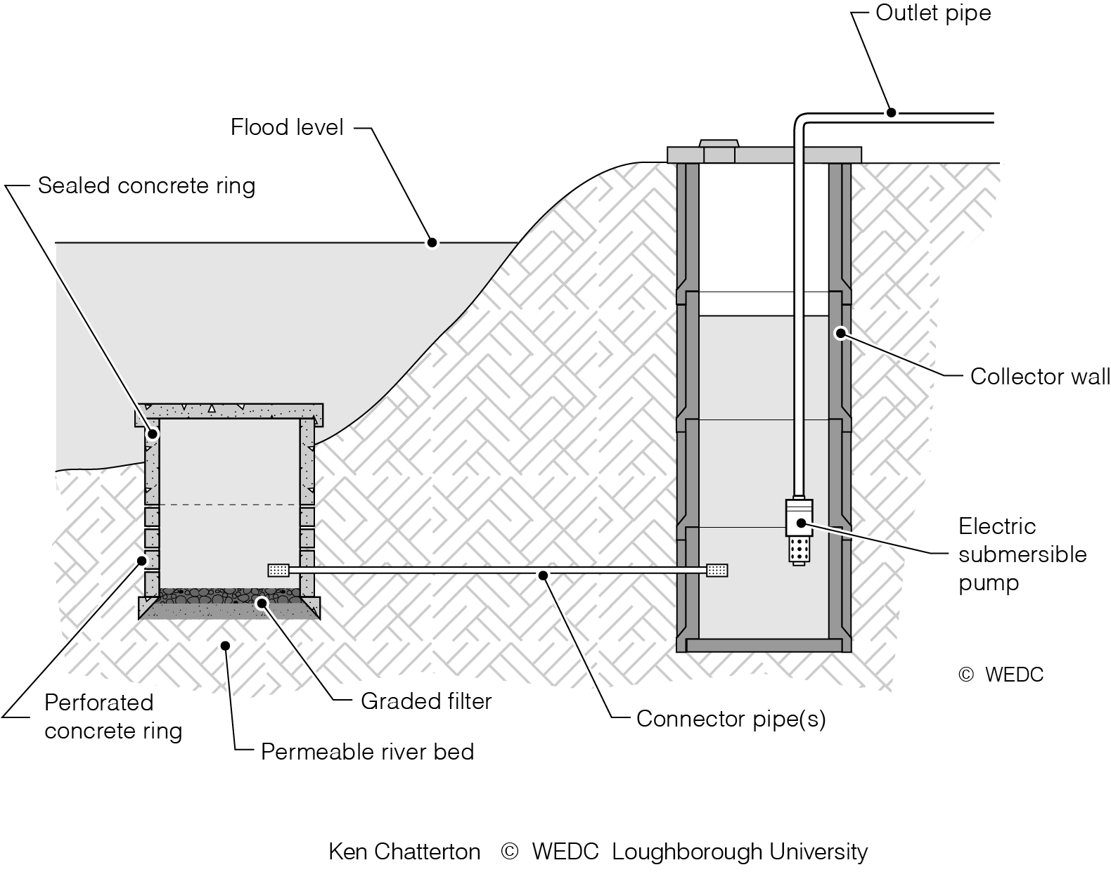
4-8 Saline Intrusion into groundwater close to the coast | 5-10 Infiltration trench filled with sand and gravel | 5-11 Infiltration well made of concrete rings sunk into the river bed | ||
|
|
| ||
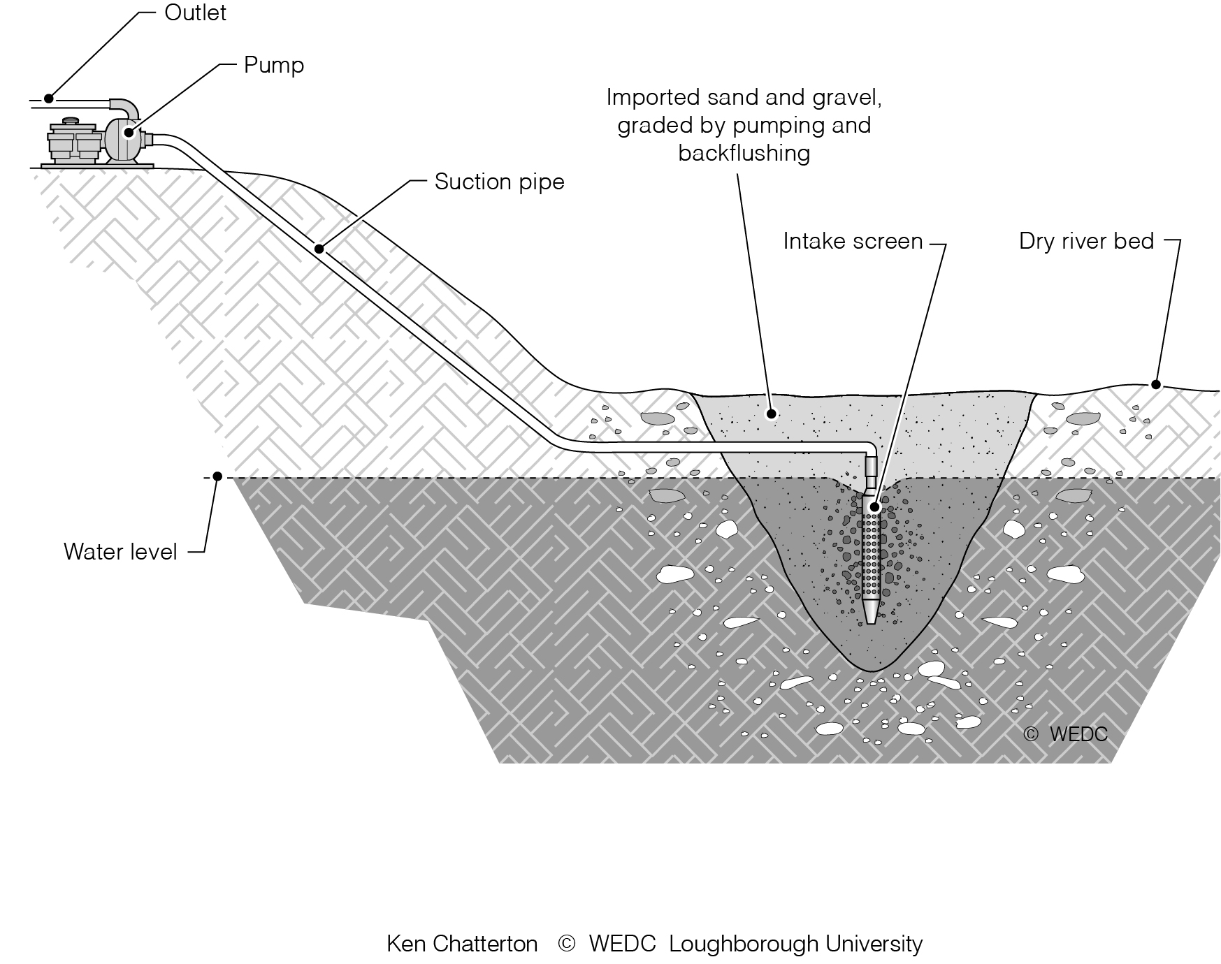
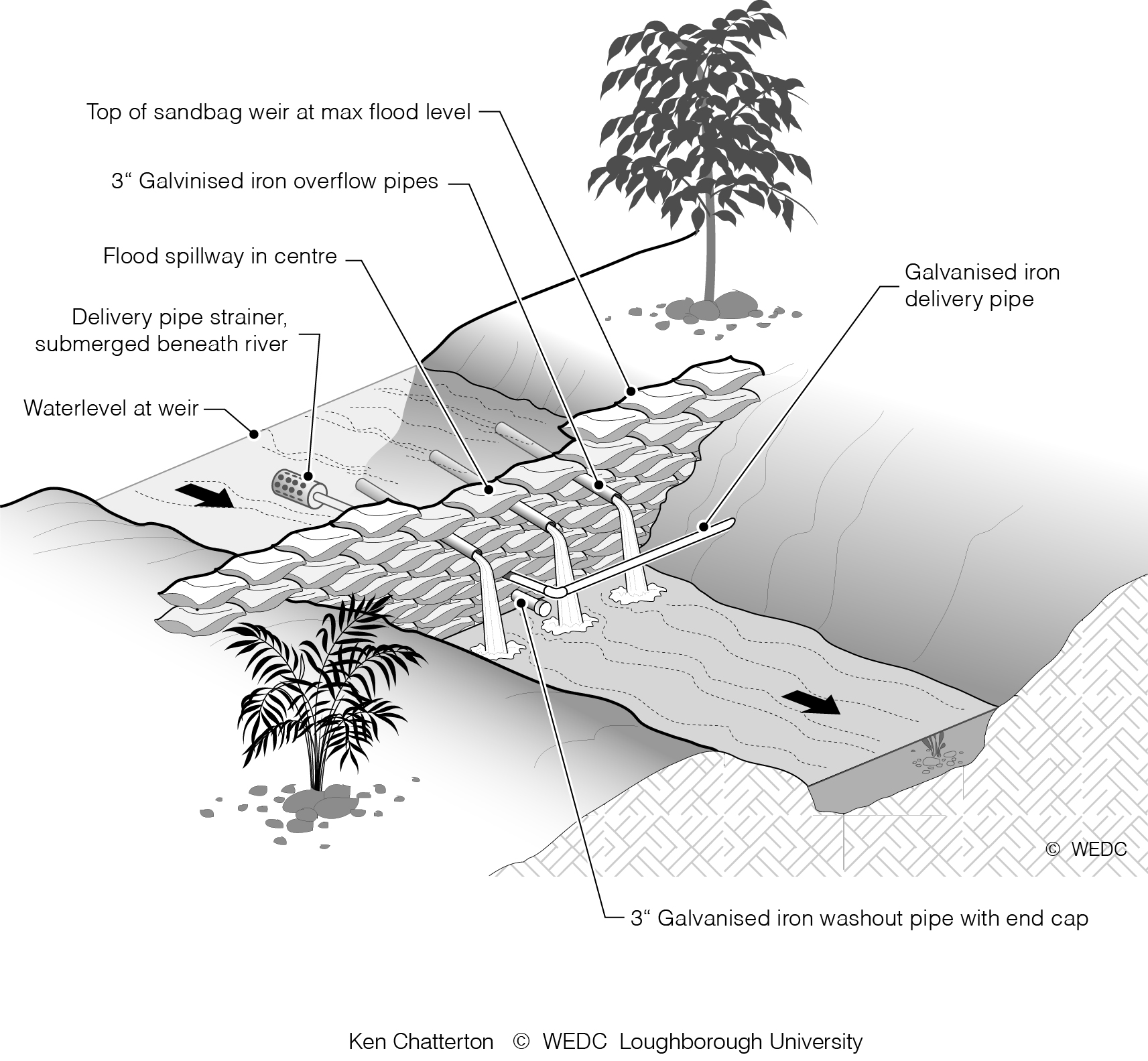
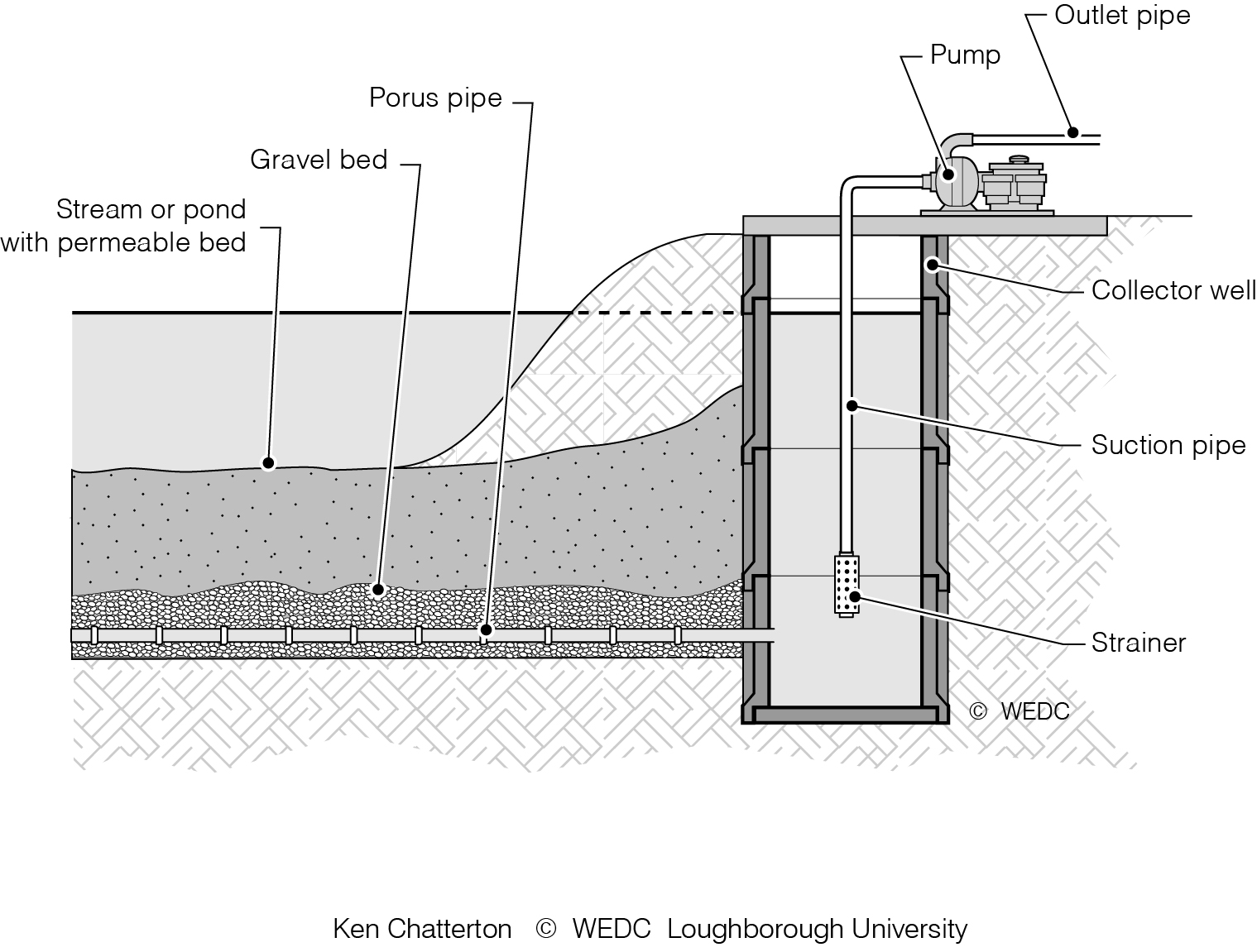
5-12 Infiltration well using a pipe with screened intake | 5-13 Bank side infiltration gallery | 5-14 Temporary weir made of sand bags | ||
|

|
| ||
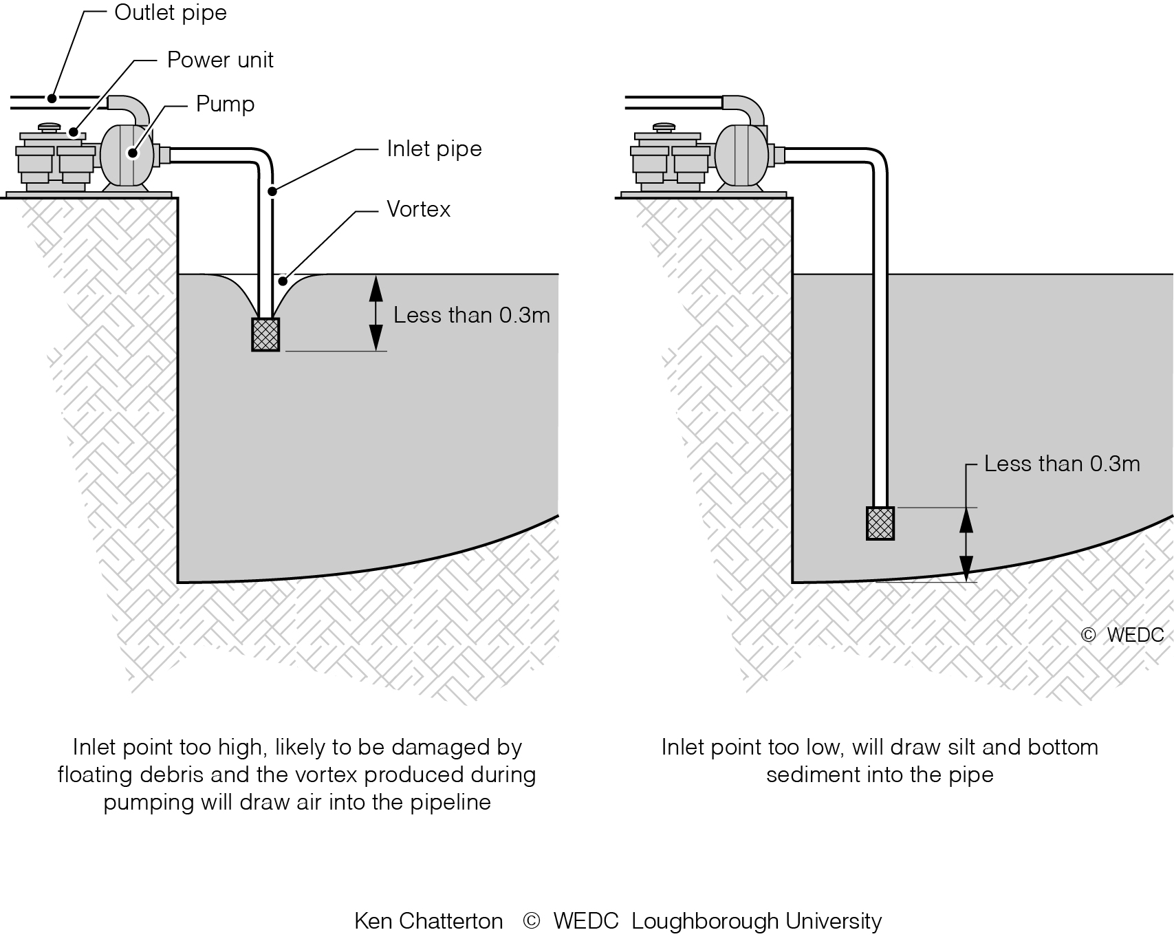
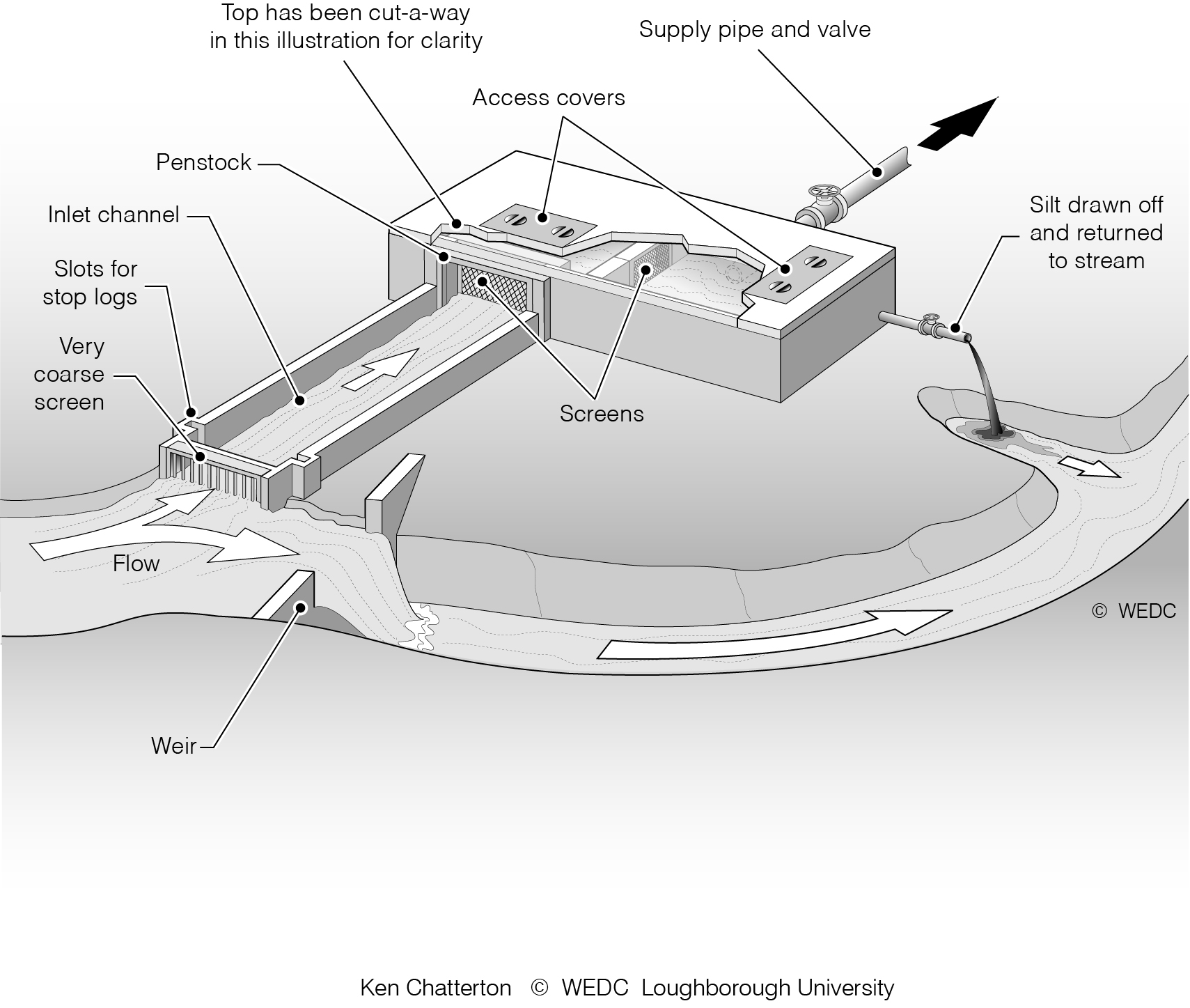
5-1 Problems caused if the pipe inlet is too near the surface | 5-2 Simple arrangements of pump section inlets | 5-3 Intake using side channel and screen | ||
|
|
| ||
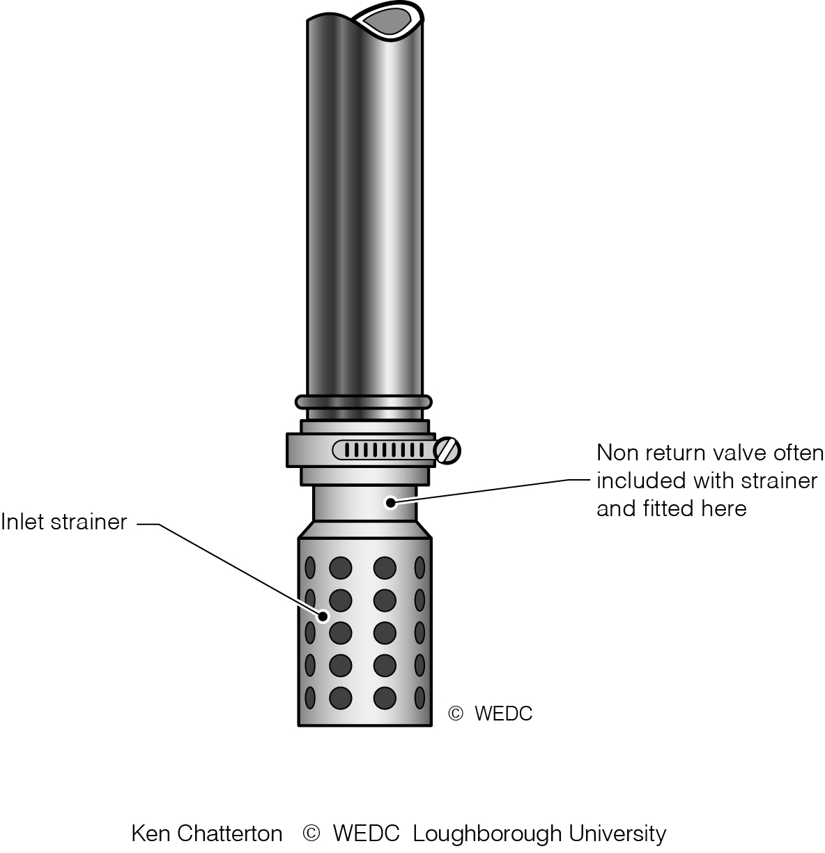
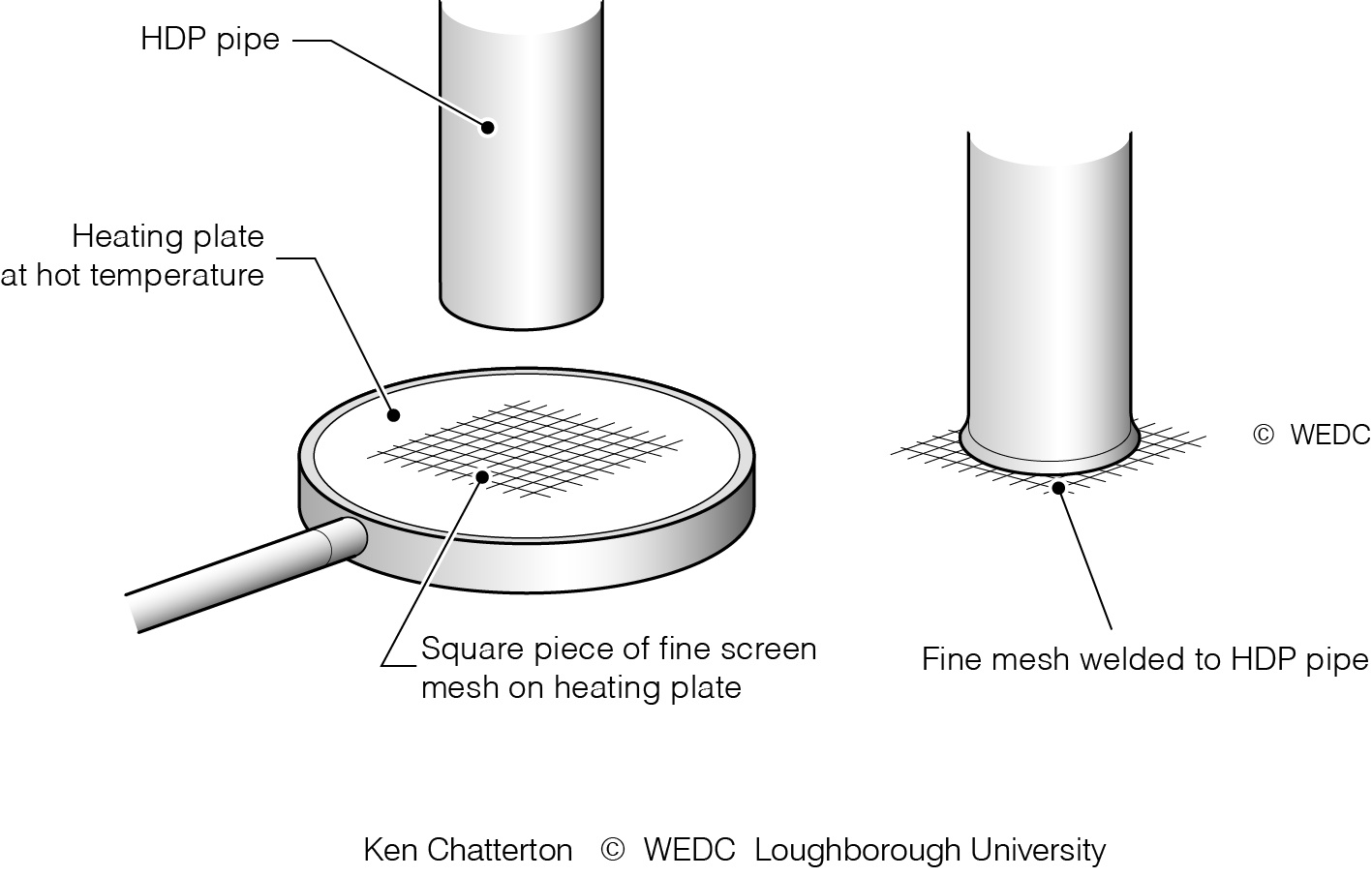
5-4 Prefabricated inlet strainer for a pipe | 5-5 Heat welding a fine mesh to the inlet of a water pipe | 5-6 Submersible pump | ||
|
|
| ||
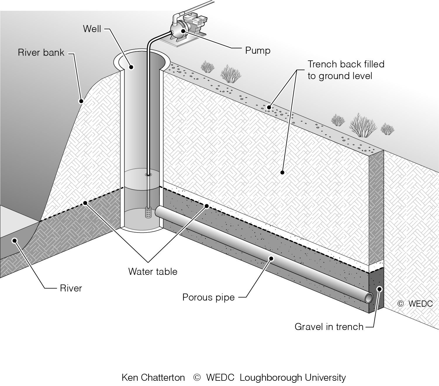
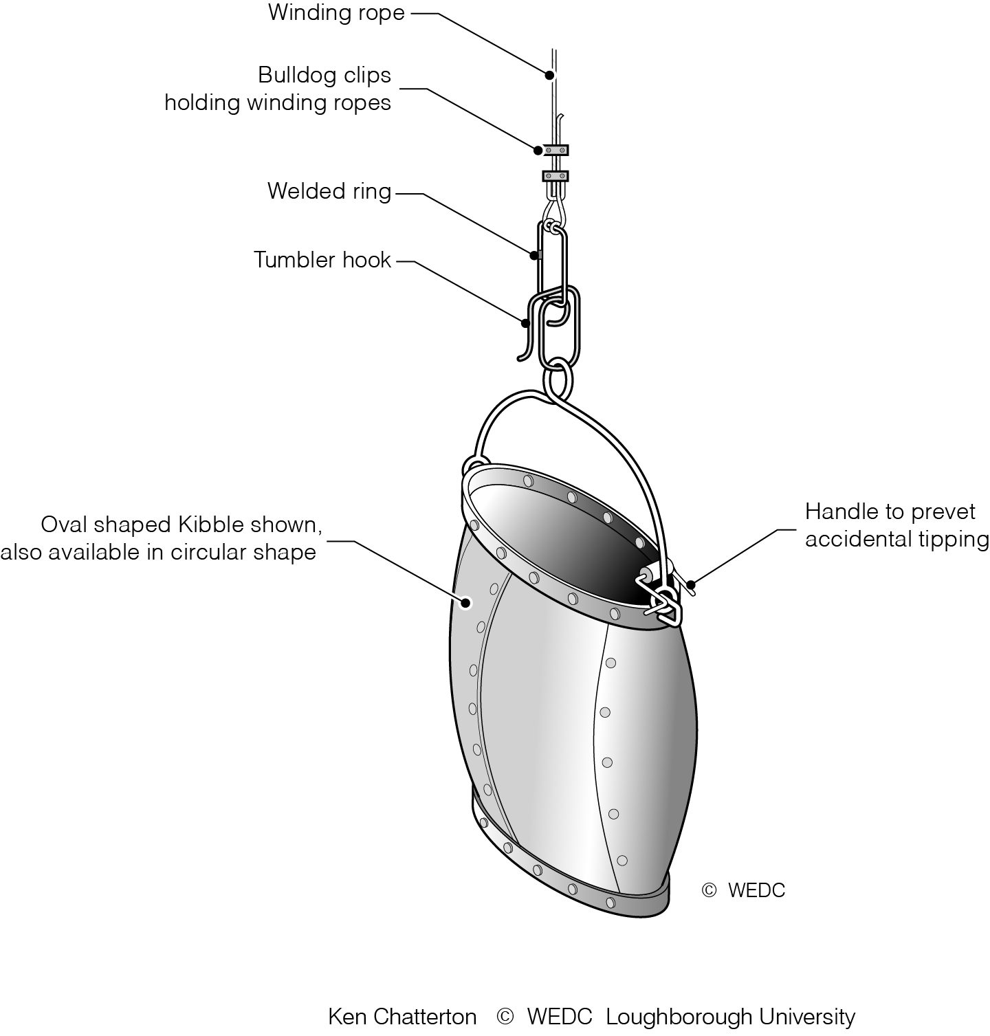
5-8 Infiltration well | 5-9 Hand dug well close to river bank drawing water from the aquifer connected to the river | 6-10 Kibble bucket for lifting and lowering material into wells | ||
|
|
| ||
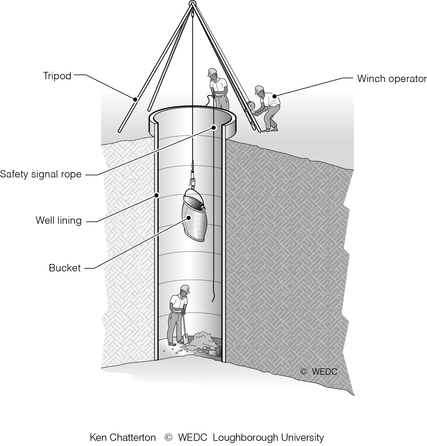
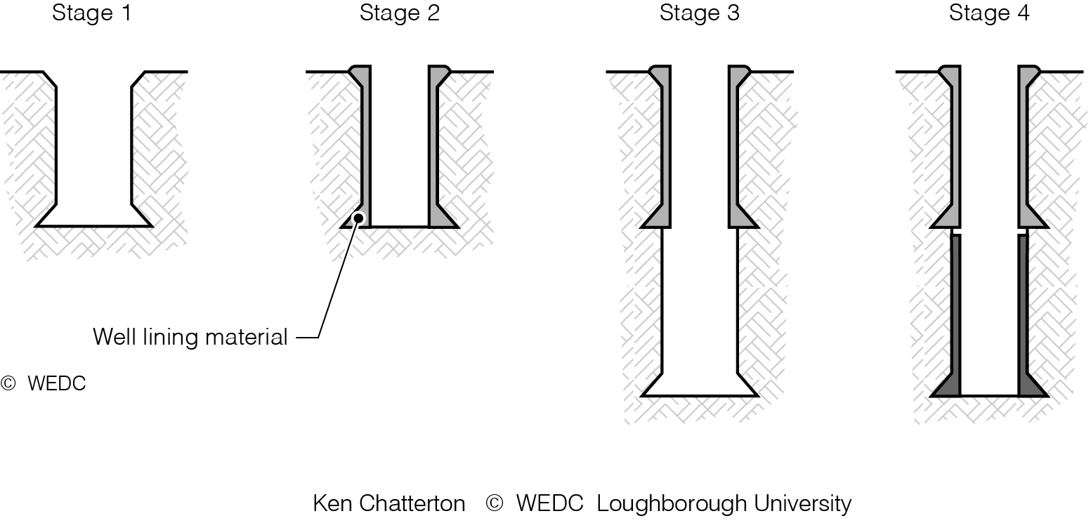
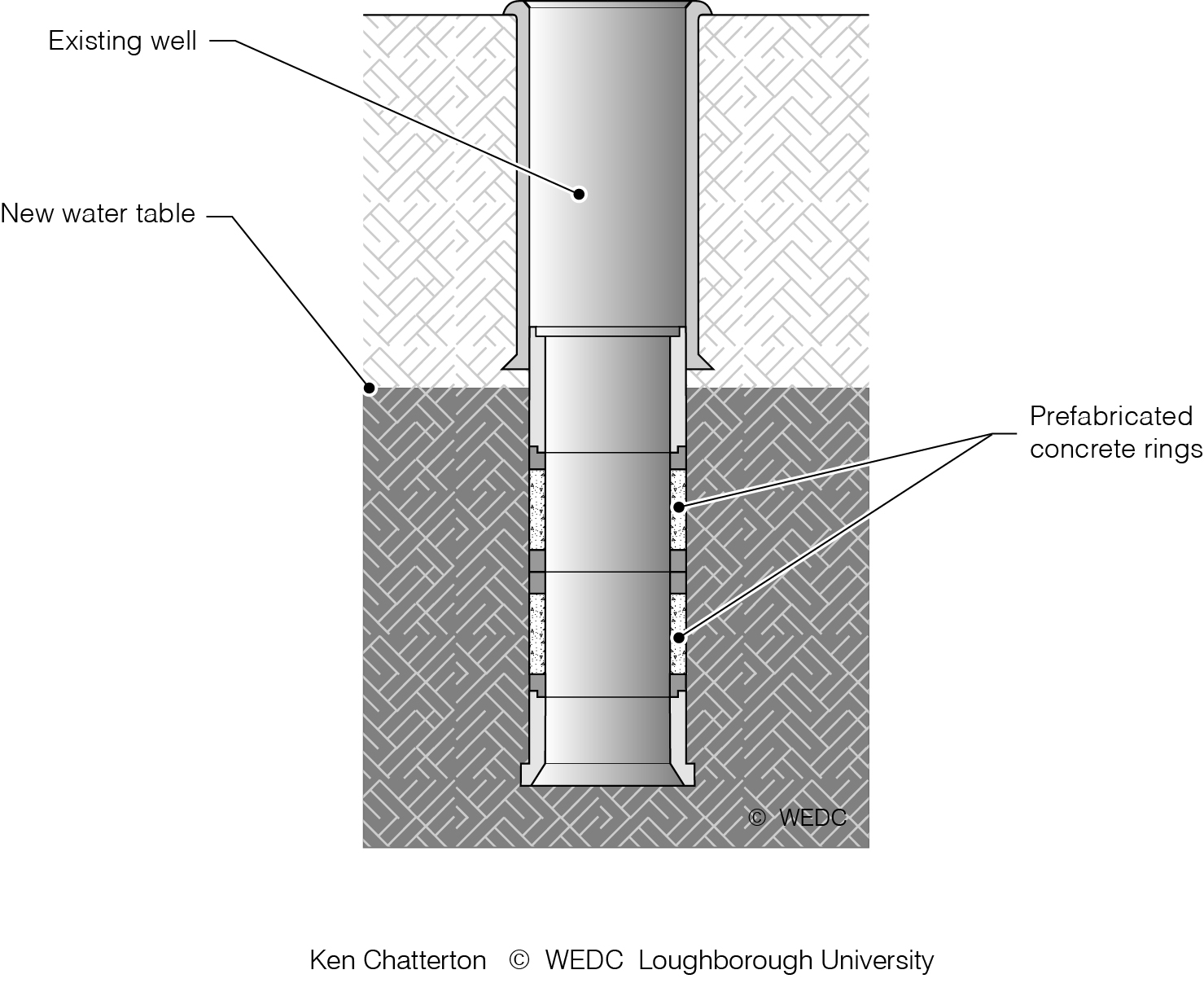
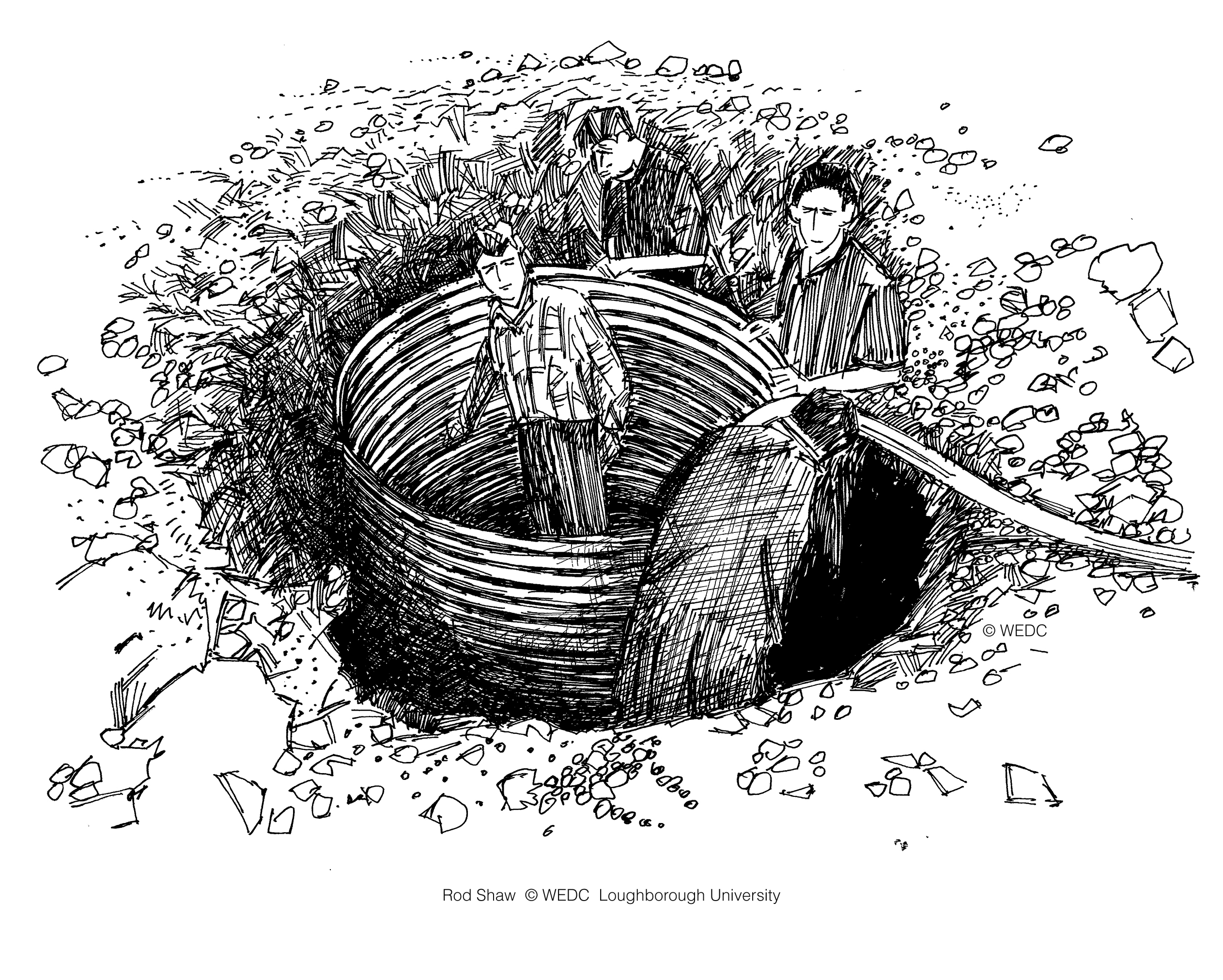
6-11 Constructing a shallow well showing use of tripod and winch for raising and lowering materials | 6-12 Lining a well in sections - concrete block work or brick | 6-14 Increasing the depth of existing well by caissoning | ||
|
|
| ||
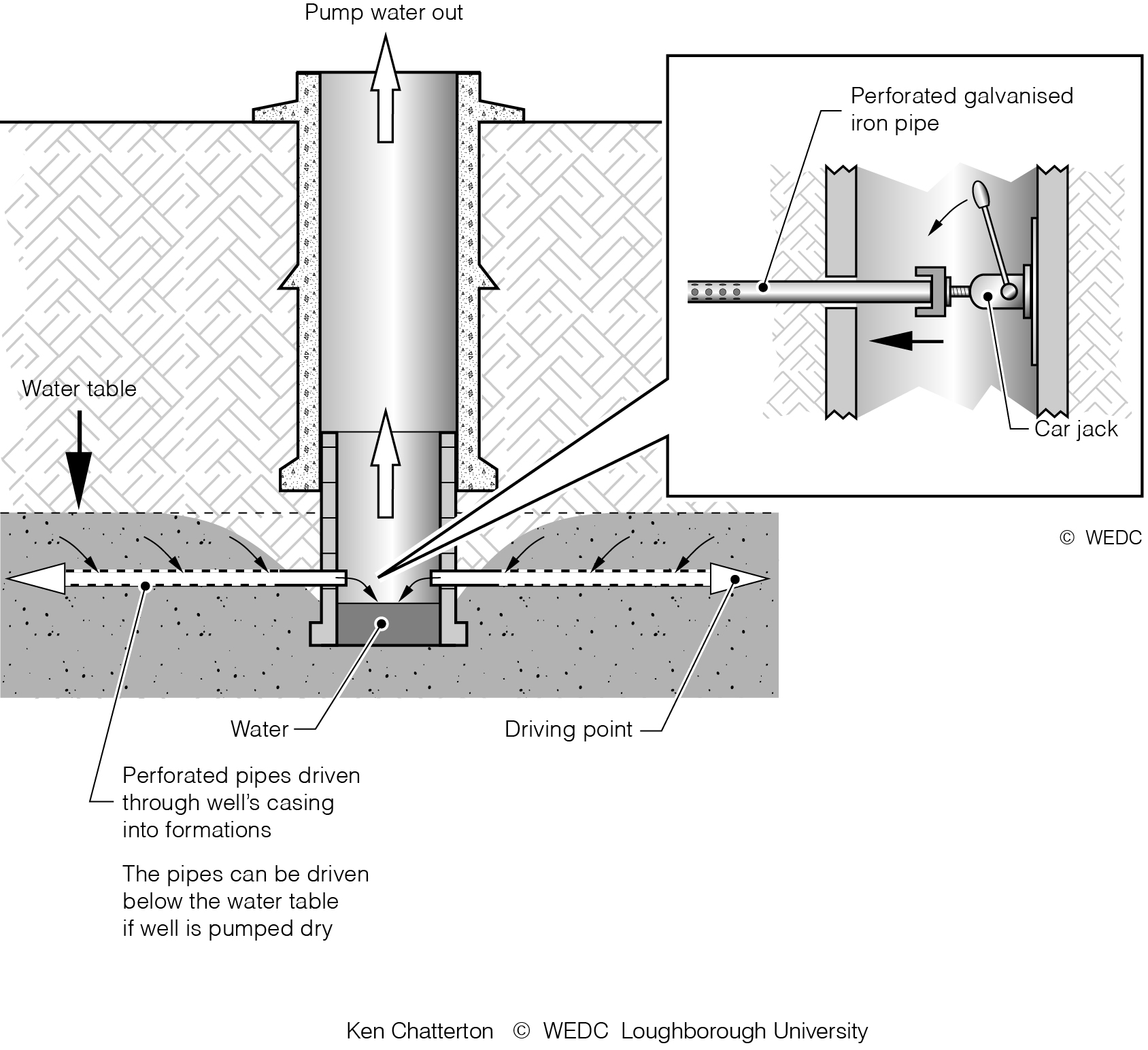
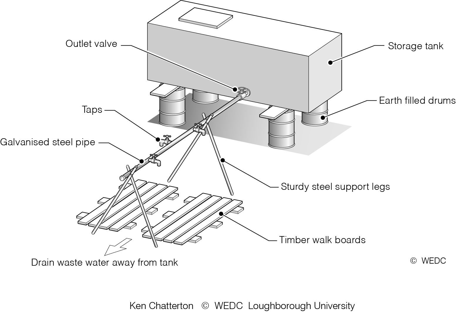
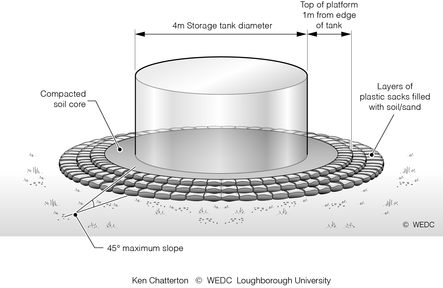
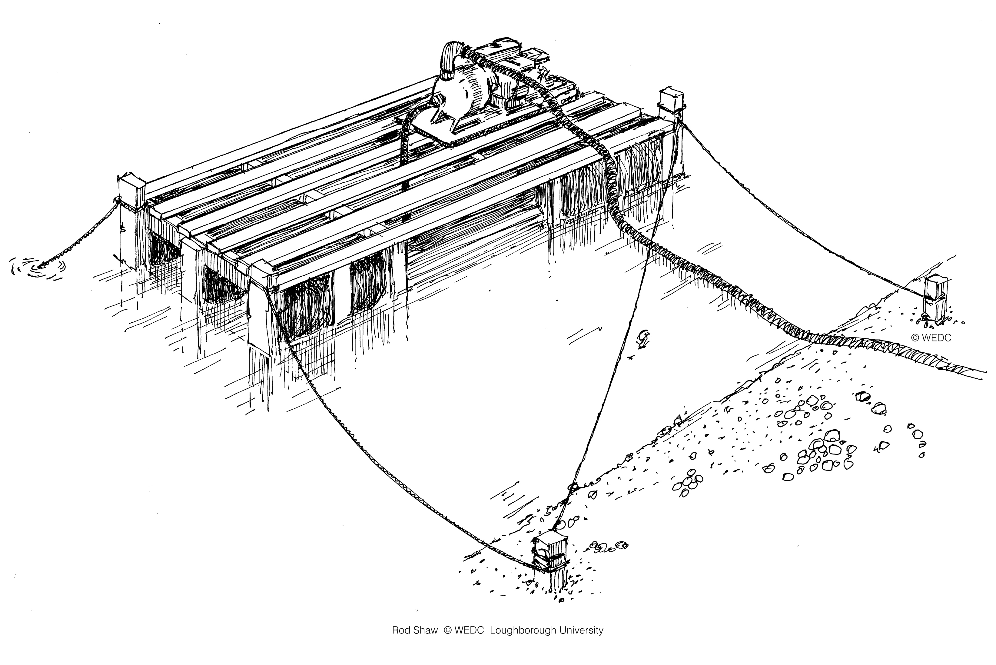
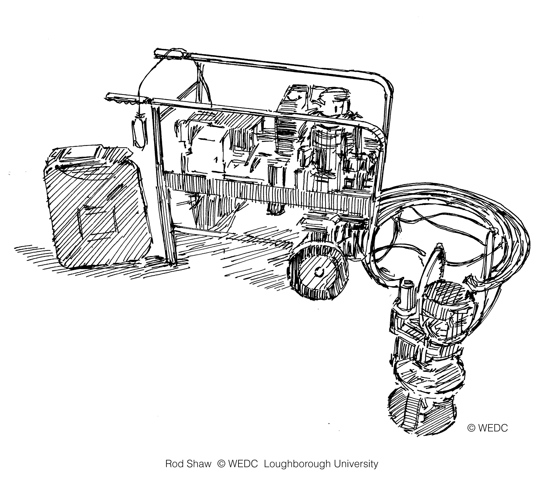
6-15 Increasing well yield by driving perforated pipes into well wall below aquifer | 7-10 Temporary water distribution point with rigid tank elevated on sand filled storage drums | 7-11 Raised platform for a storage tank supported by retaining wall of sand-filled sacks | ||
|
|
| ||
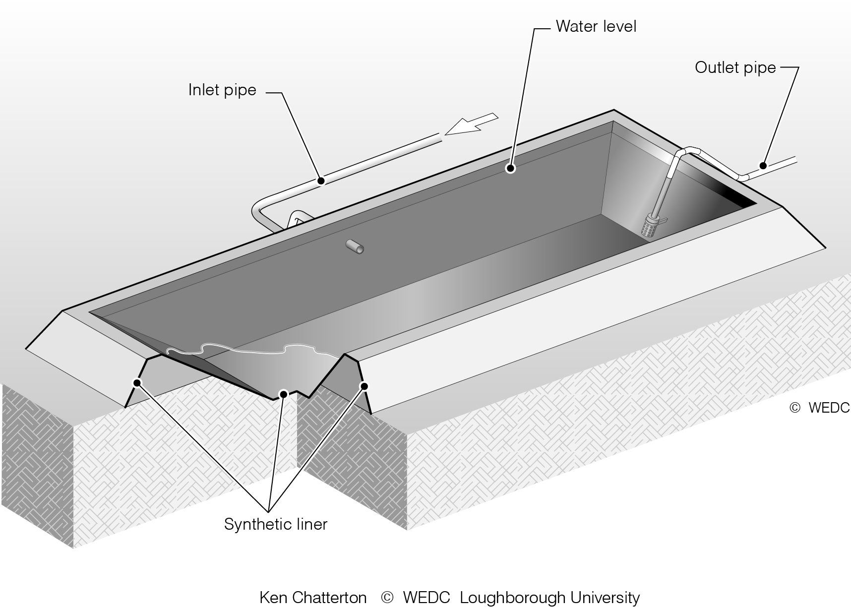
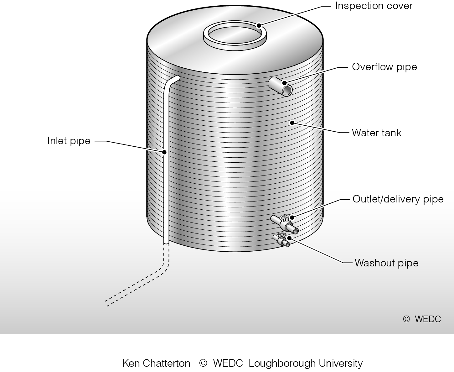
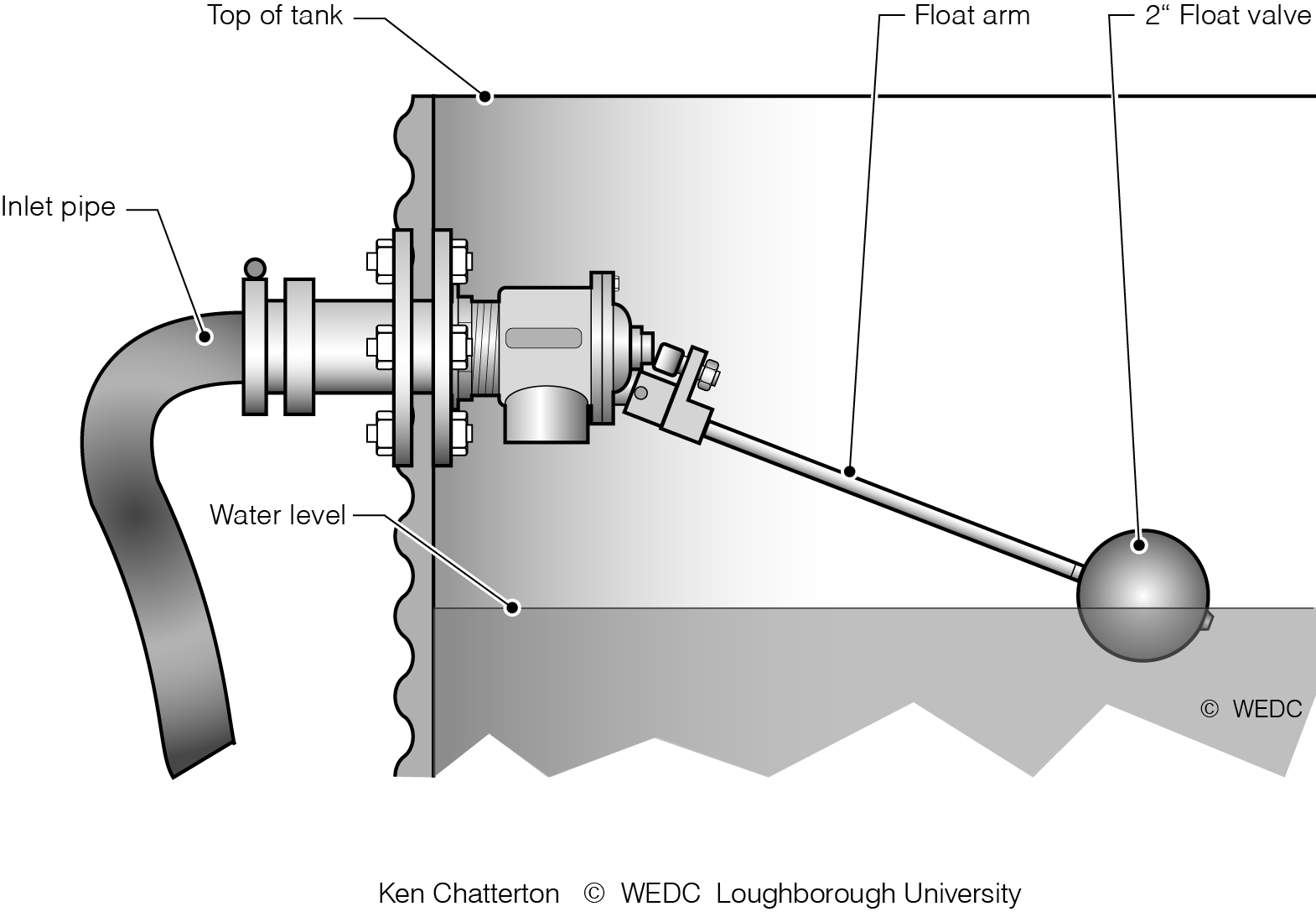
7-13 Below ground storage tank with synthetic liner | 7-4 Schematic layout of storage tank pipework | 7-5 Ball float valve fitted to inlet pipe | ||
|
|
| ||
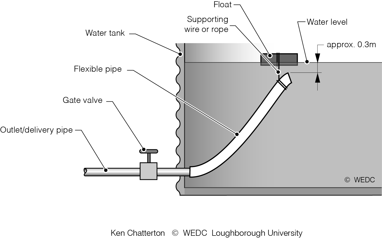
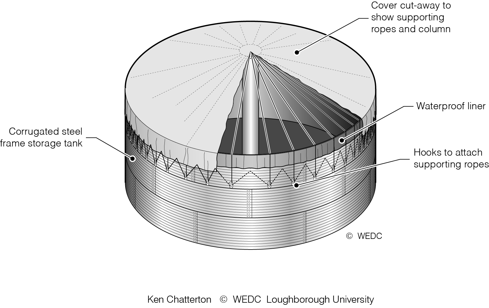
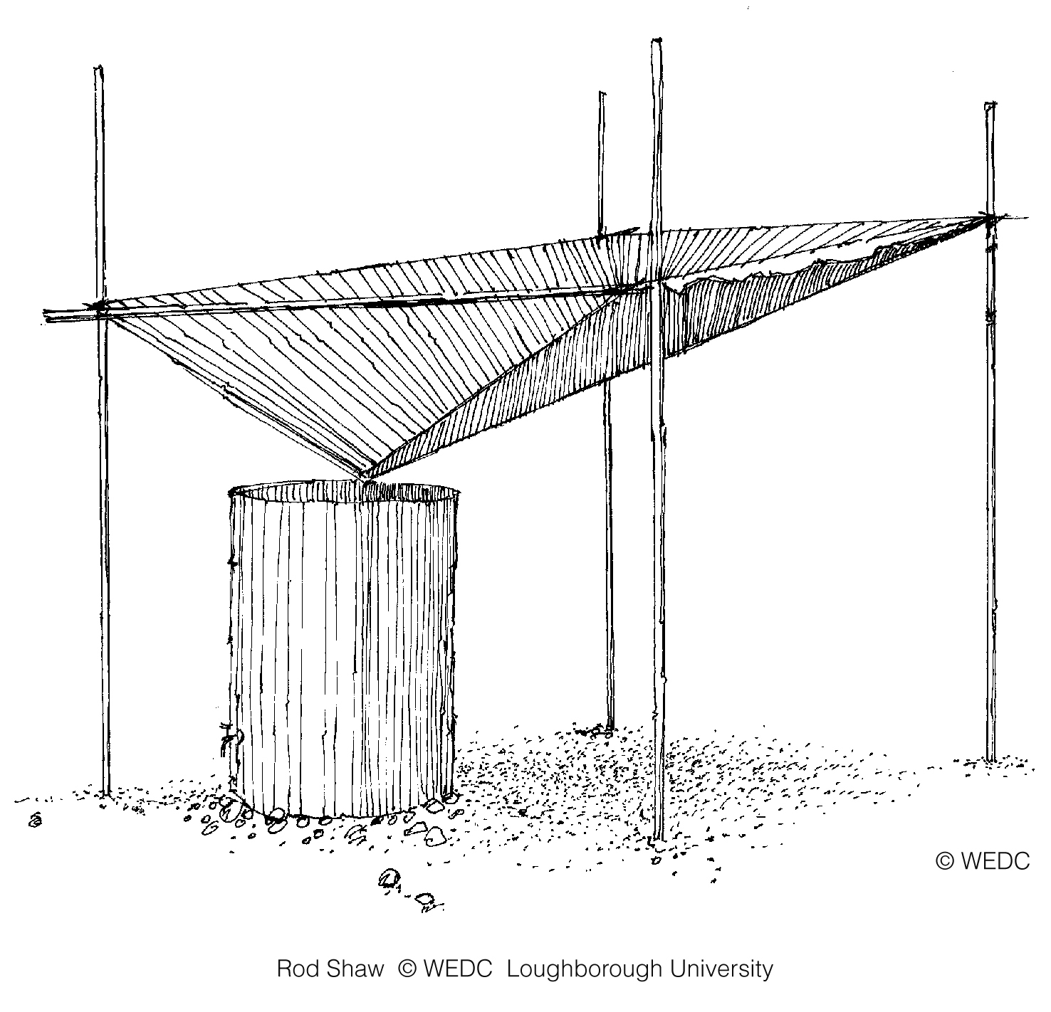
7-6 Tank outlet fitted with air vent | 7-7 Floating outlet | 7-8 Fabric cover to storage tank cutaway showing column and ropes | ||

|
|
| ||
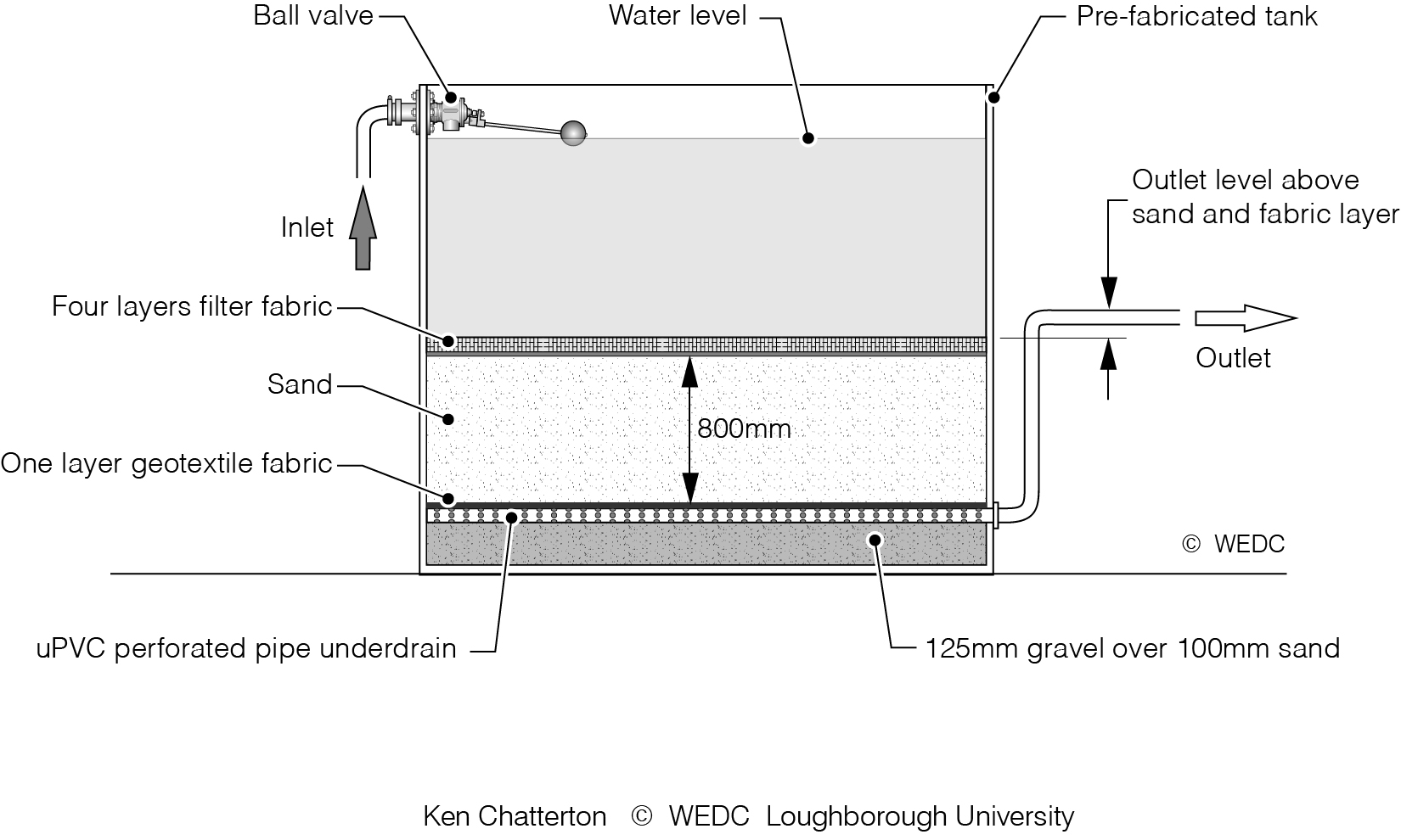
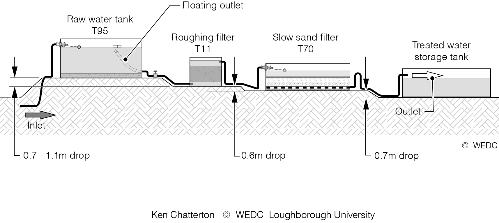
8-10 Oxfam clarifier using two 30 metre lengths of hose | 8-12 Layout of slow sand filter installed in a rigid framed prefabricated tank | 8-13 Process layout for using a slow sand filter | ||
|
|
| ||
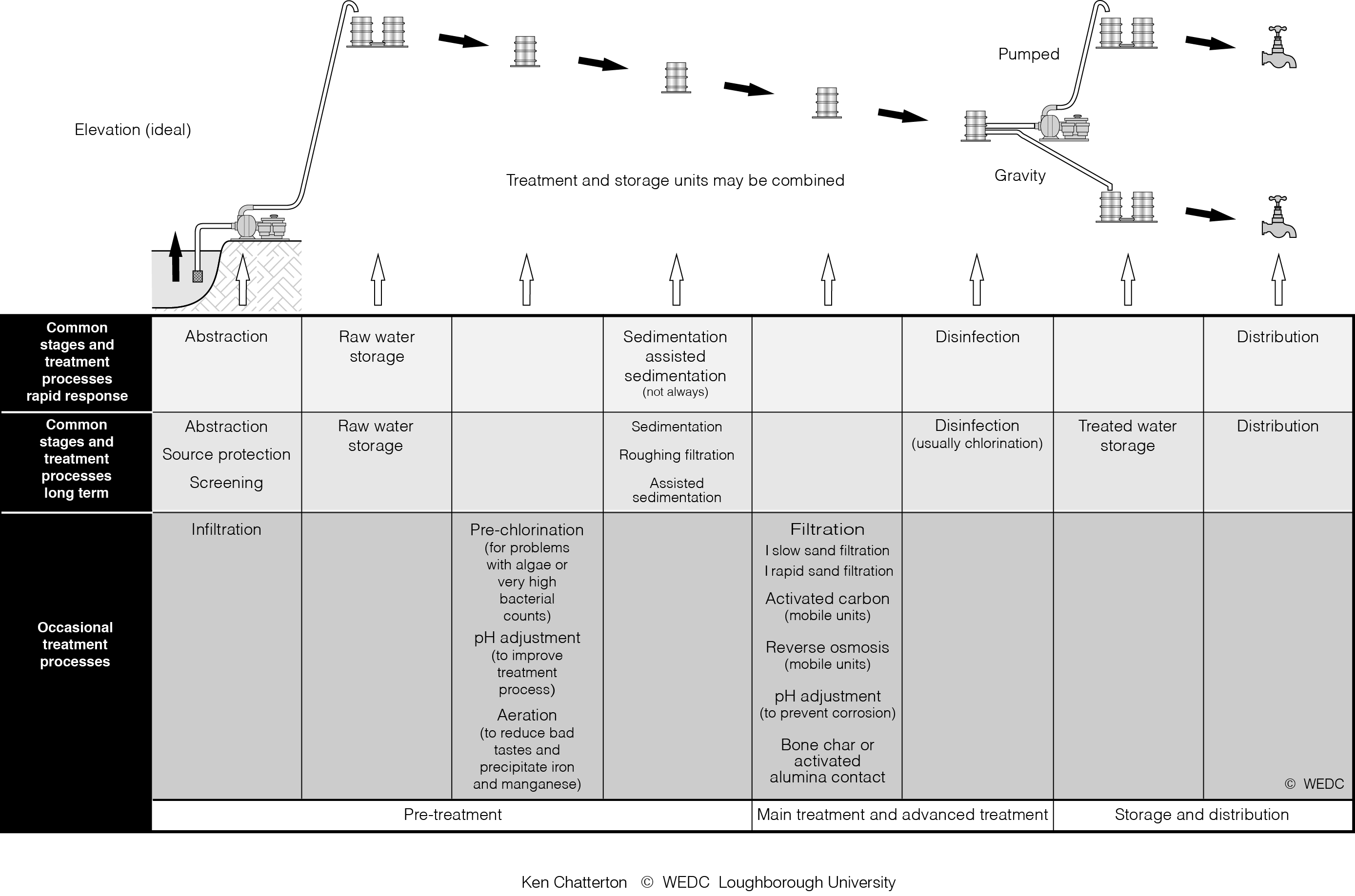
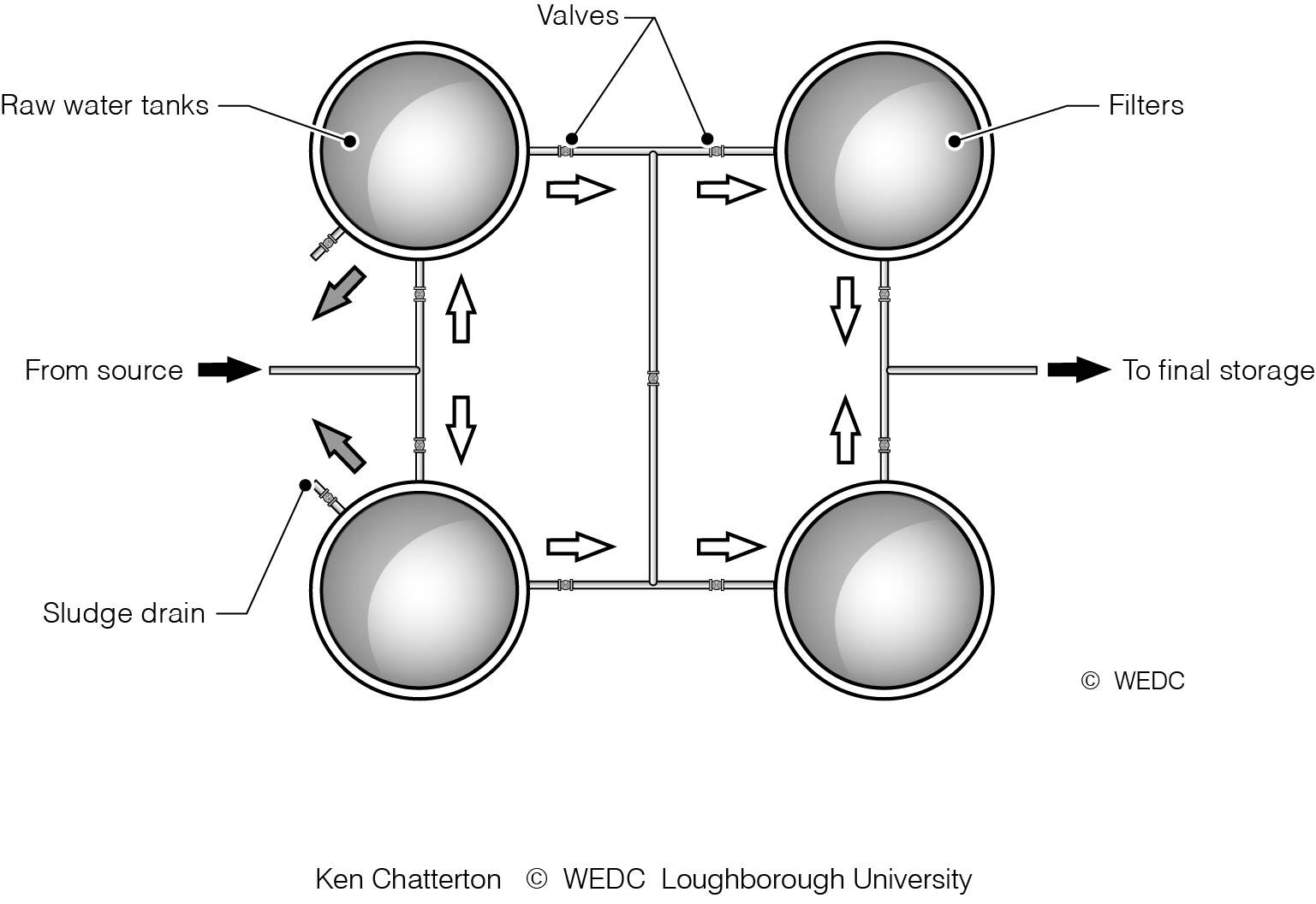
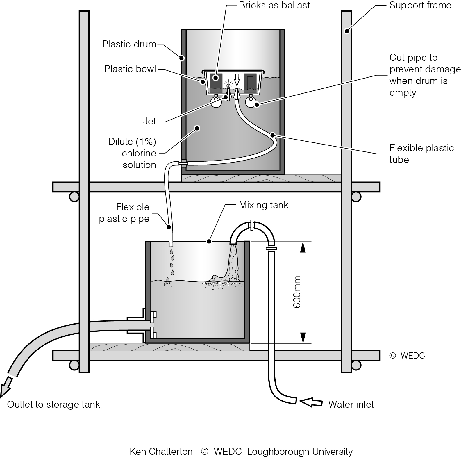
8-1 Linkage of water treatment processes for various stages in an emergency | 8-2 Parallel treatment processes | 8-3 Constant rate chlorinator | ||

|
|

| ||
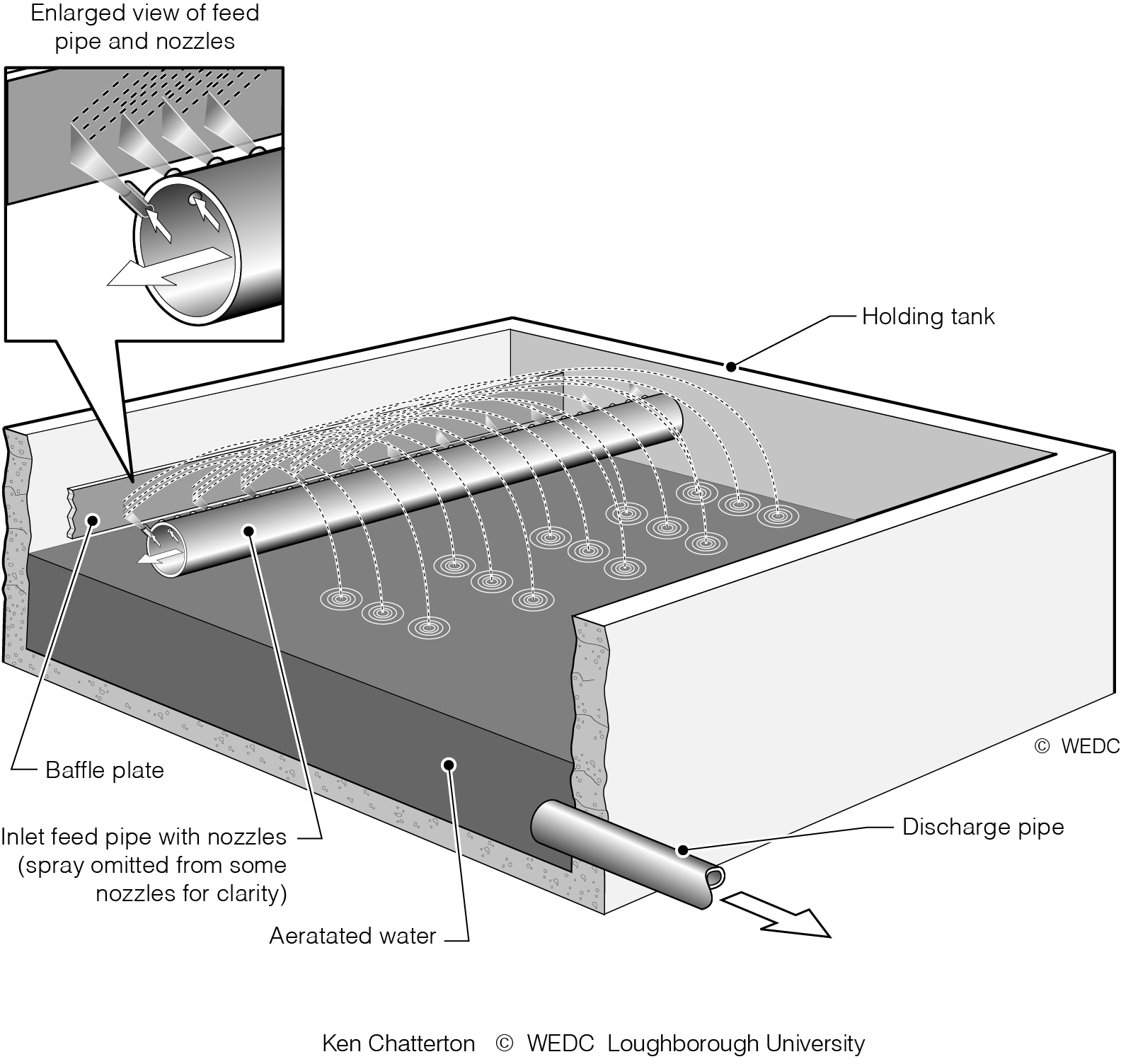
8-4 Displacement doser | 8-5 Simple spray aerator | 8-6 Batch sedimentation tank with diffuser inlet | ||

|
|

| ||
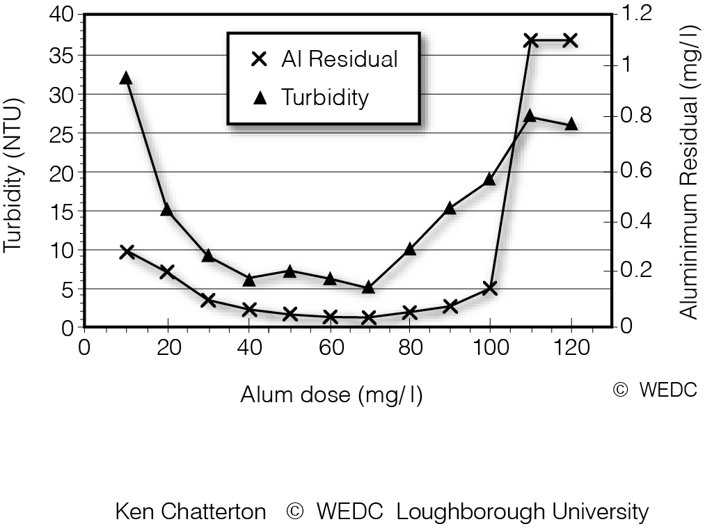
8-7 Locally constructed underground sedimentation tank | 8-9 Graph showing results of jar test | 9-2A Flat hose | ||

|

|
| ||
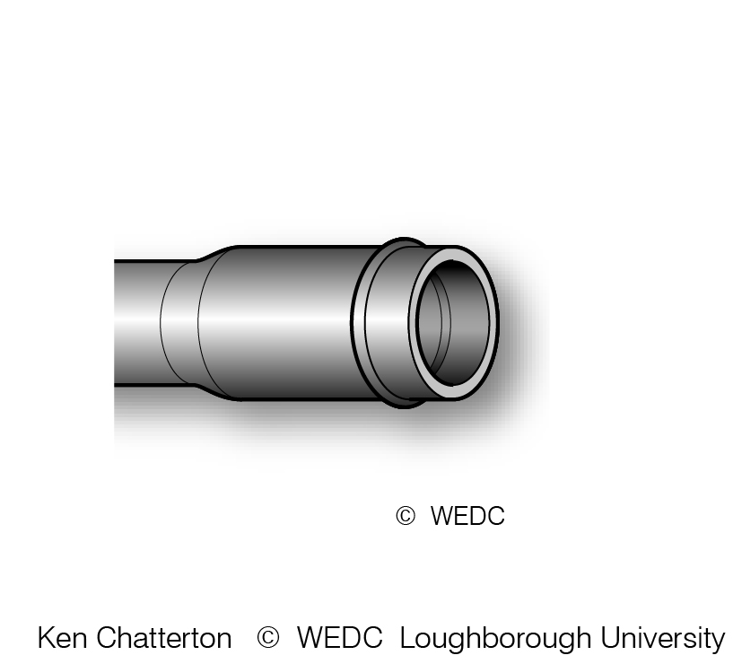
9-2B Semi-rigid hose | 9-2C Polythene pipe | 9-2D Unplasticised polyvinyl chloride pipe | ||

|
|

| ||
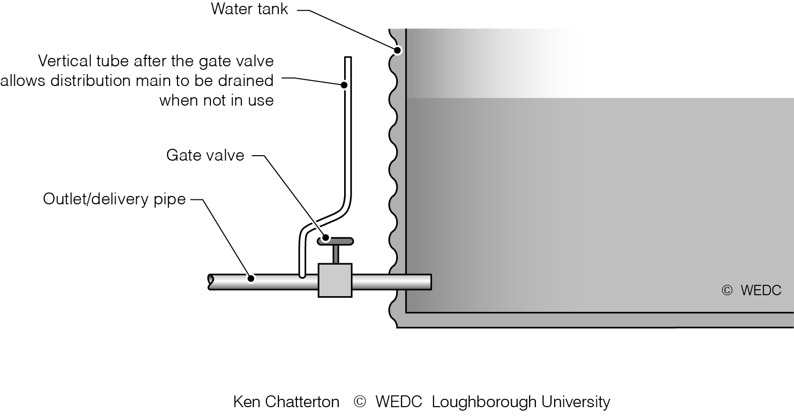
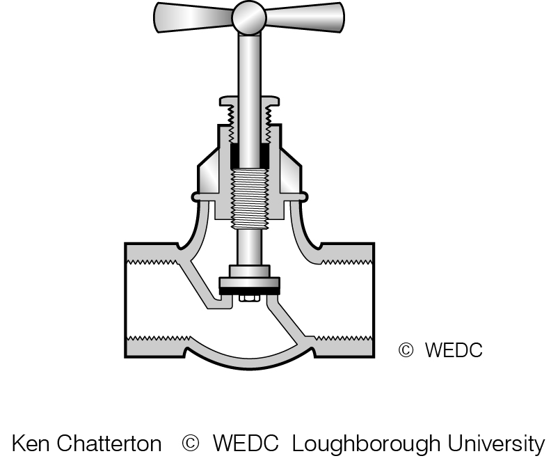
9-2E Galvanised steel pipe and coupling | 9-3A Globe valve | 9-3B Gate valve | ||
|
|
| ||
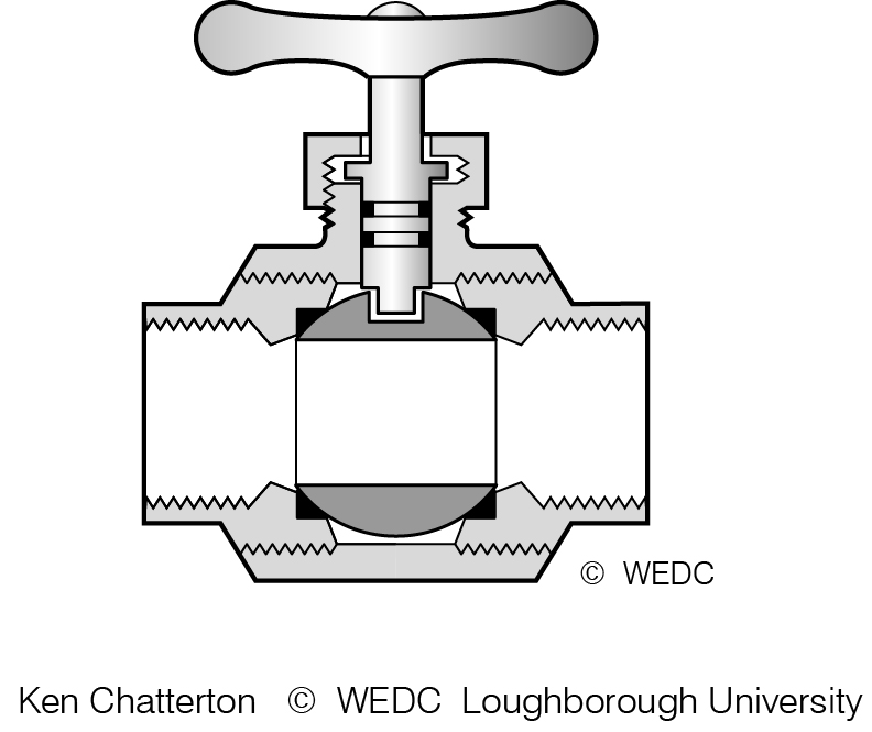
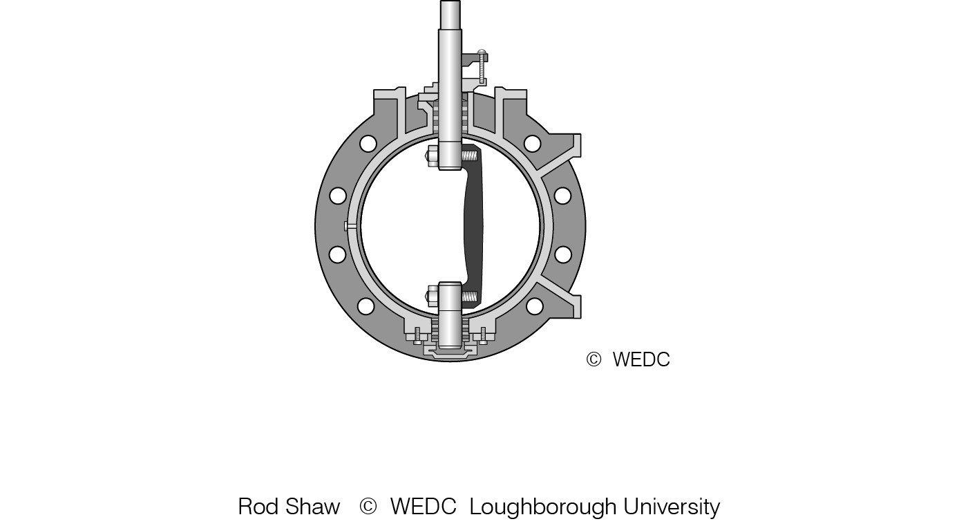
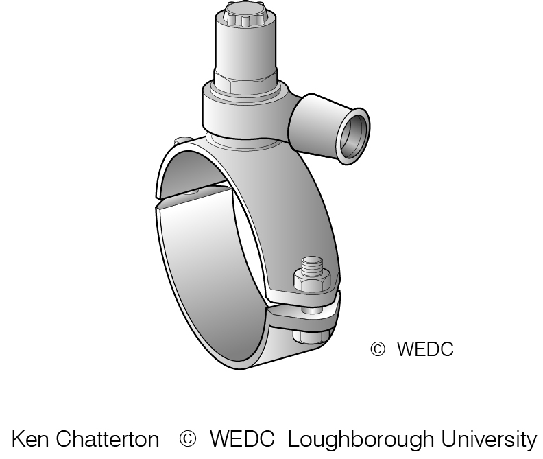
9-3C Ball valve | 9-3D Butterfly valve | 9-3E Ferrule strap | ||
|

|
| ||
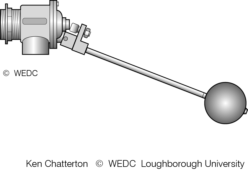
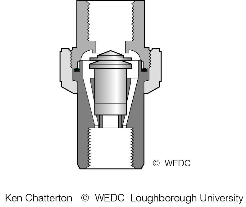
9-3F Ball float valve | 9-3G Non-return valve | 9-3H Air valve | ||
|

|
| ||
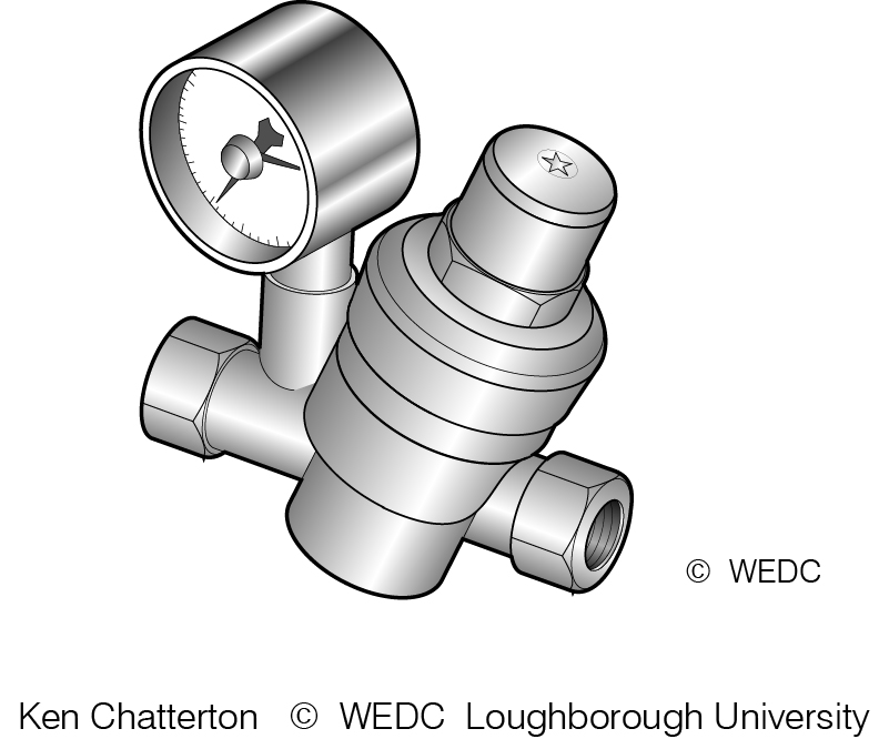
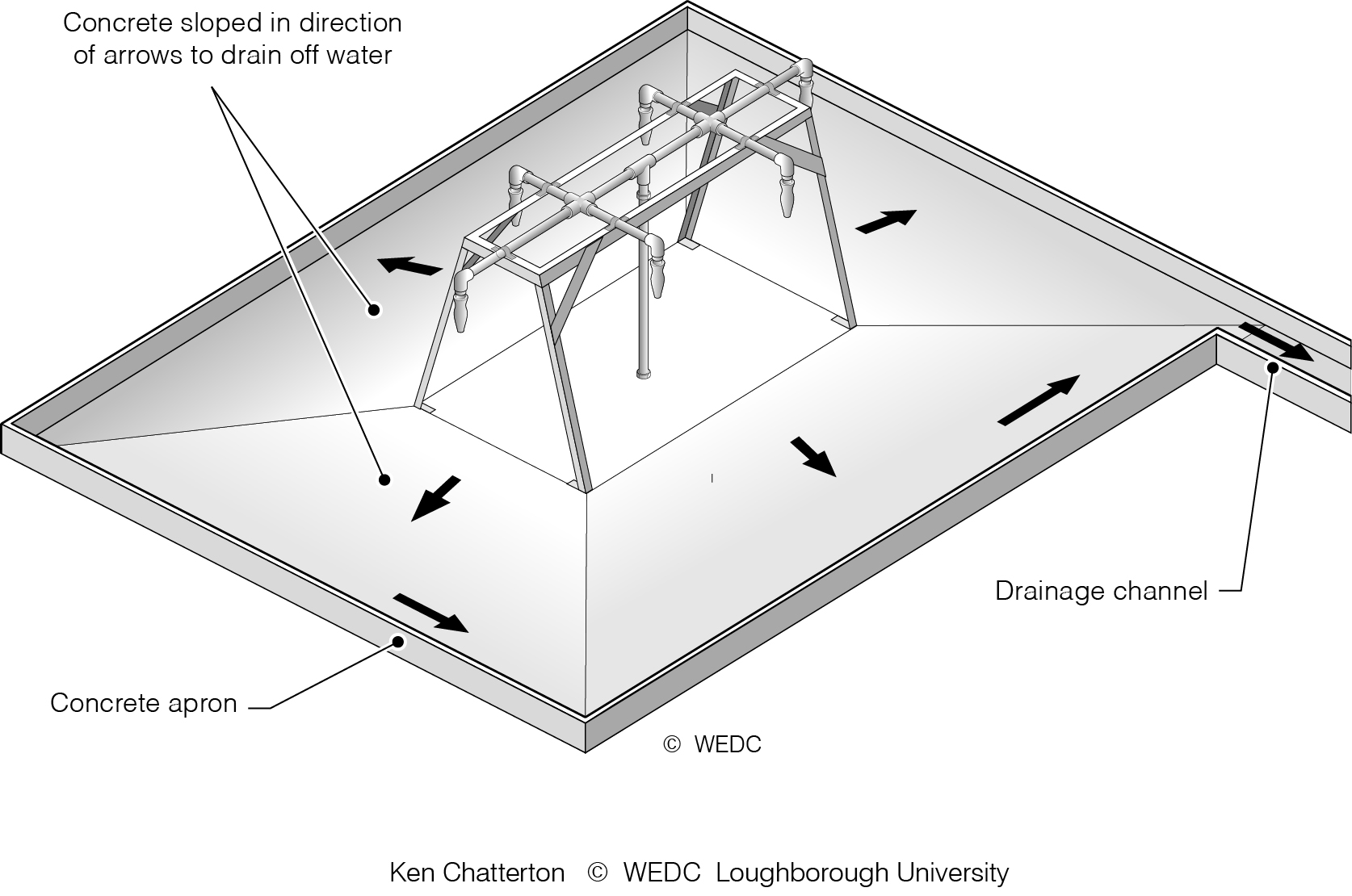
9-3I Pressure-reducing valve | 9-8 Examples of prefabricated tap stands | 9-9 Simple concrete standpost apron | ||
|

|
| ||
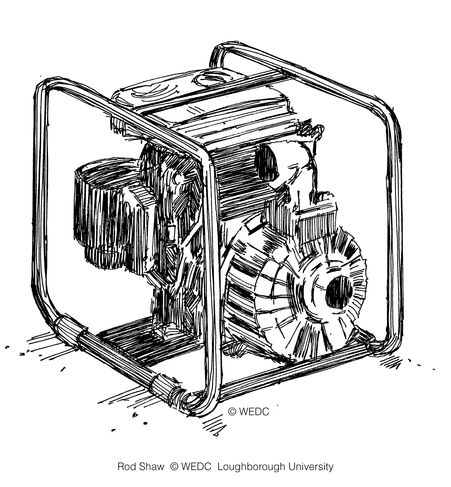
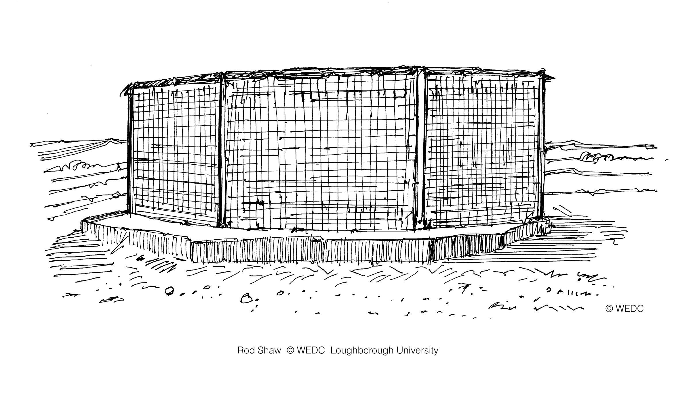
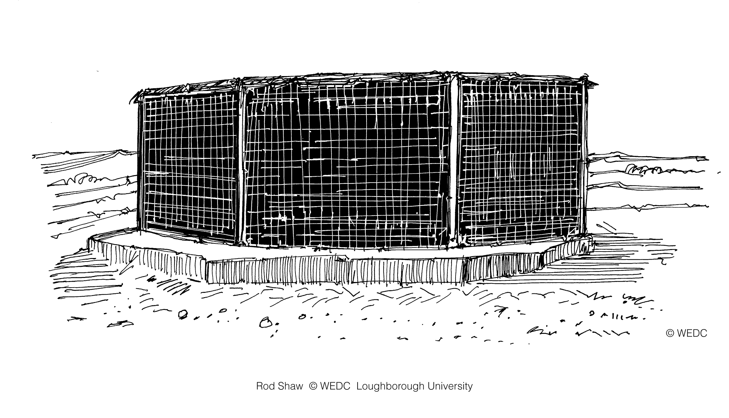
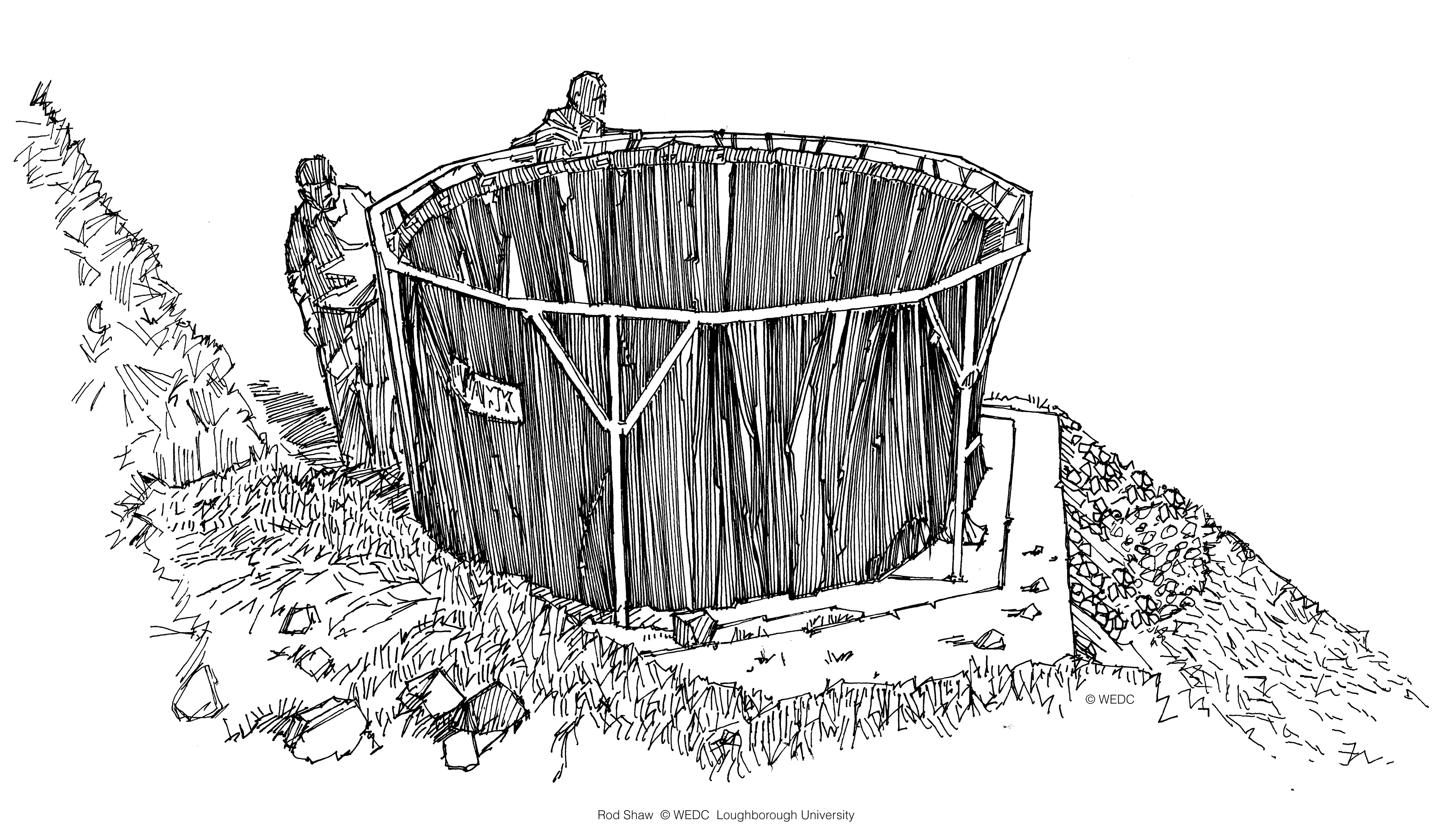
A centrifugal pump | A steel tube frame tank | A wire mesh emergency water supply tank v1 | ||
|
|
| ||
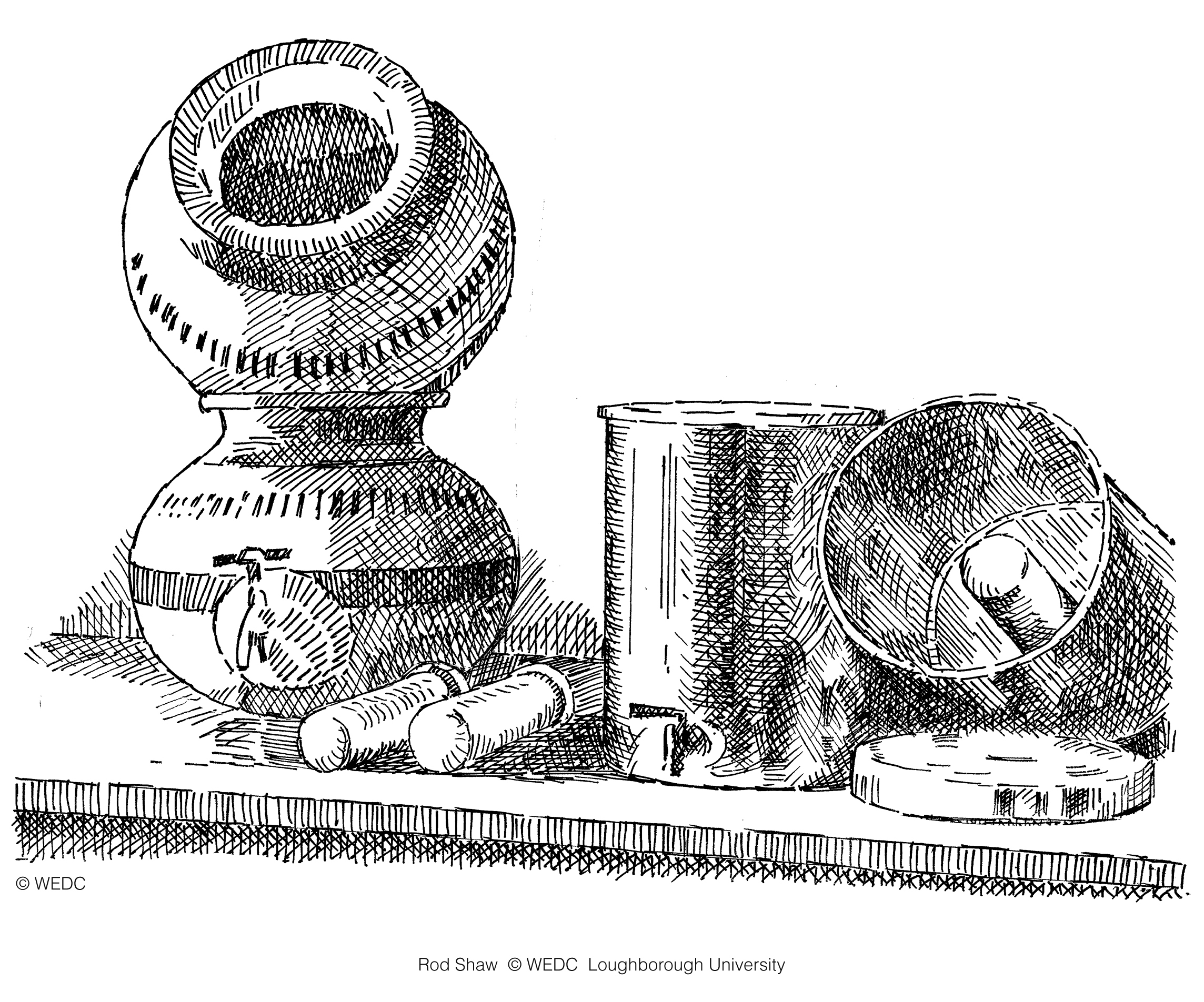
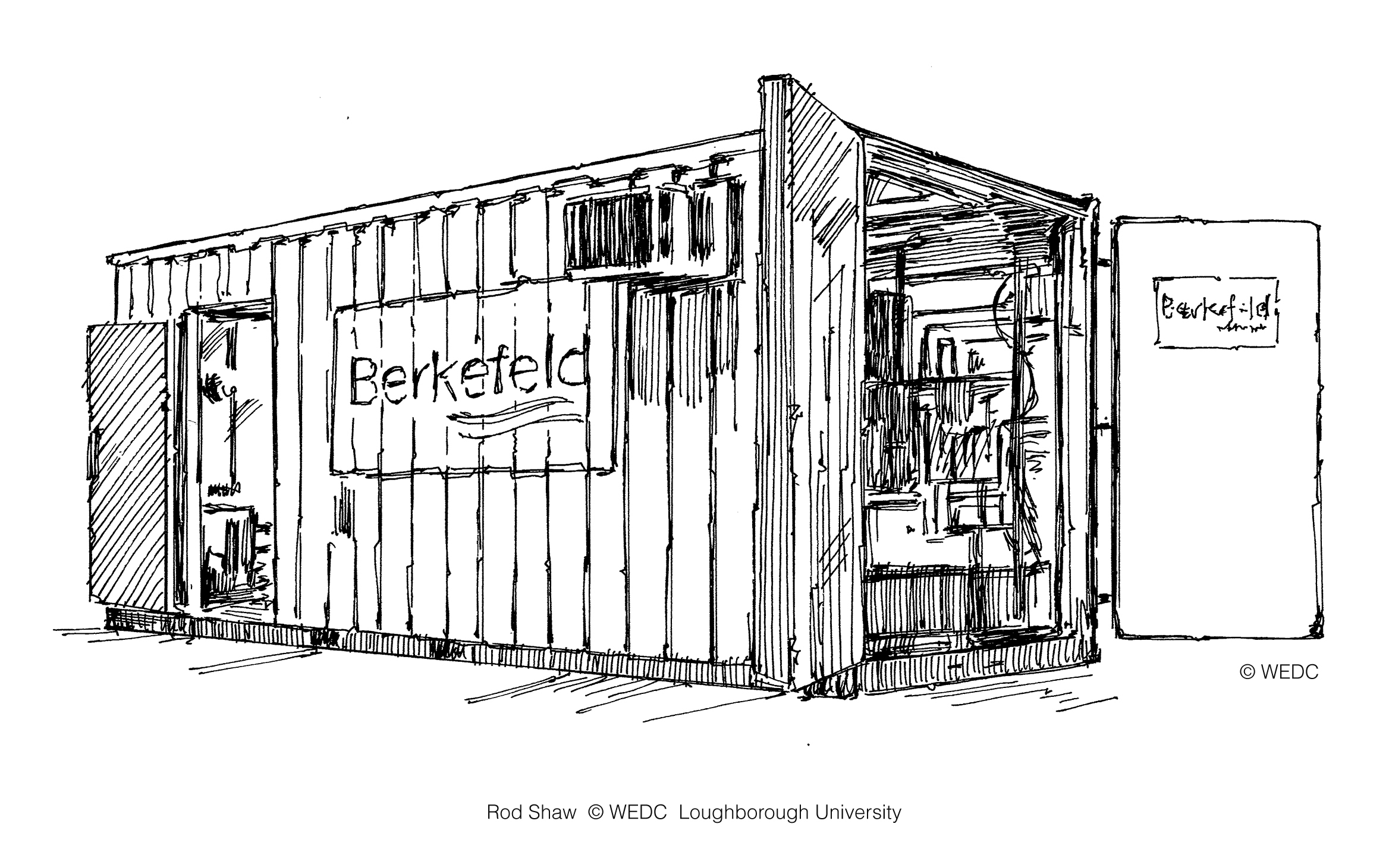
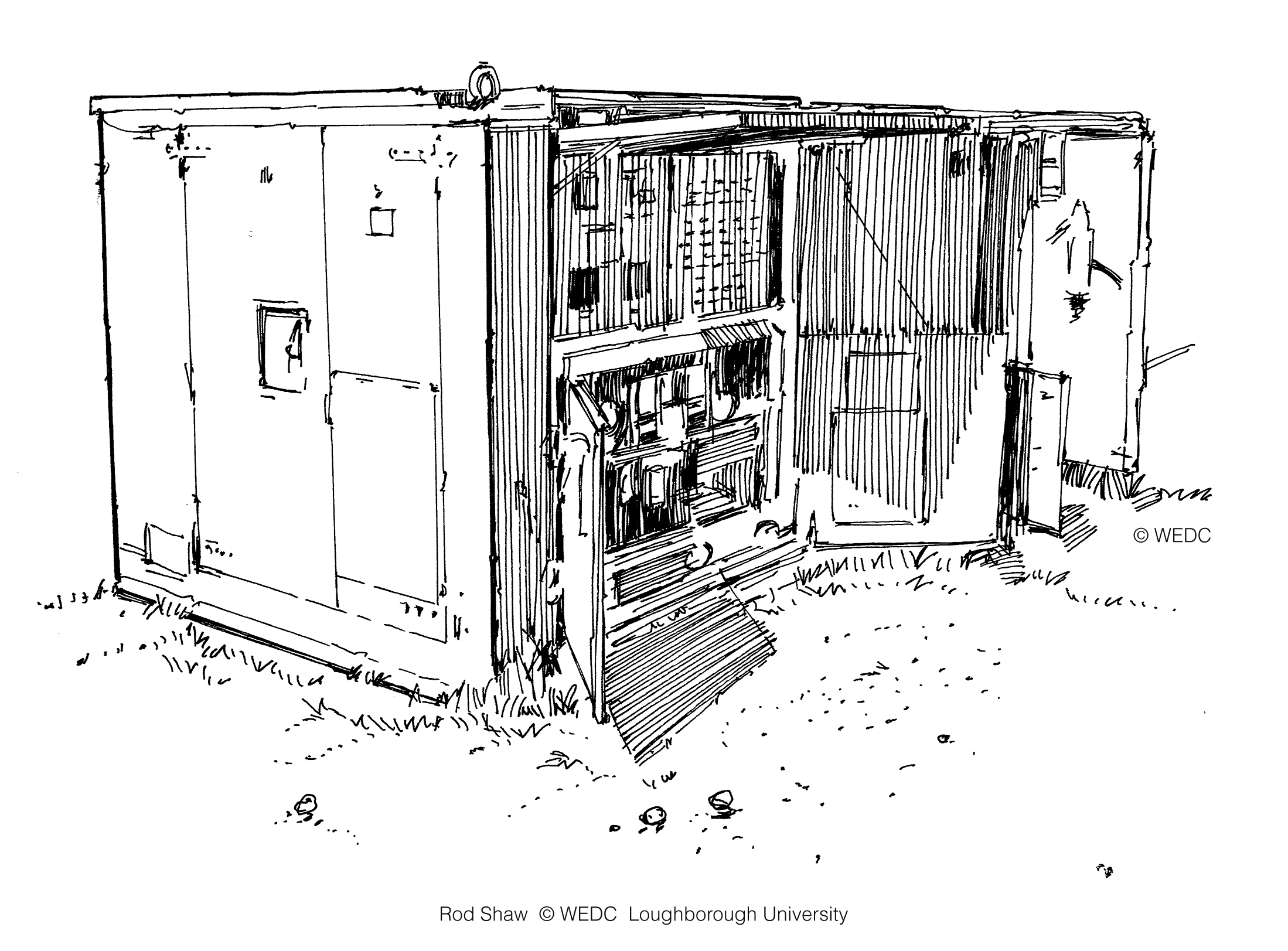
A wire mesh emergency water supply tank v2 | Candle filters 1 | Container housed mobile water treatment plant | ||
|

|
| ||
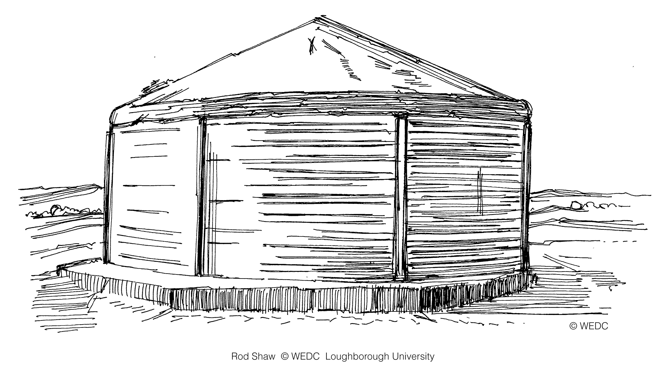
Emergency water supply tank | Emergency water tank - Oxfam v1 | Emergency water tank - Oxfam v2 | ||

|

|
| ||
Emergency water tank on a frame | Emergency water tank with two figures | Emergency water tank with two figures v2 | ||
|
|
| ||
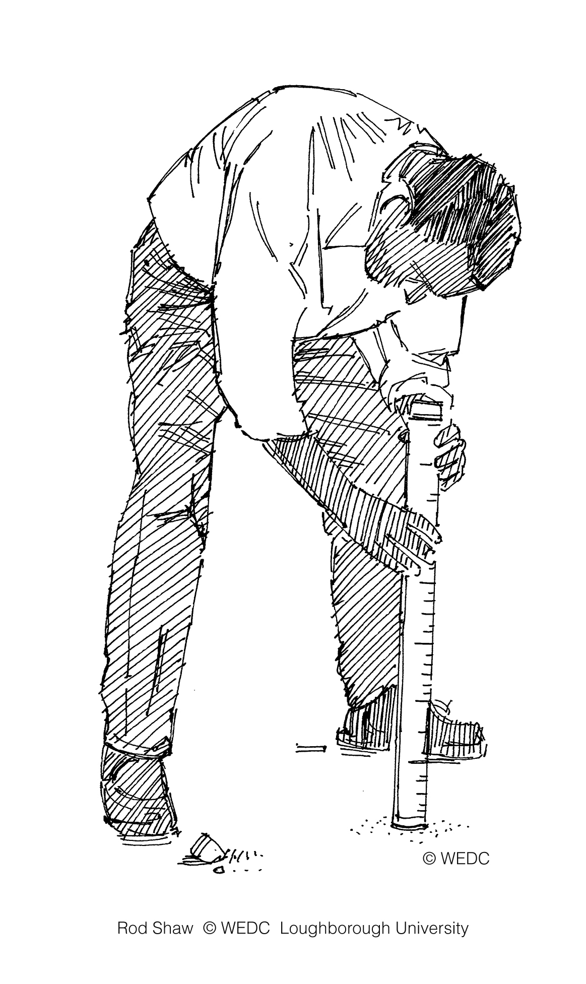
Emergency water treatment plant | Examining the turbidity of water | Floating water intake | ||

|
|
| ||
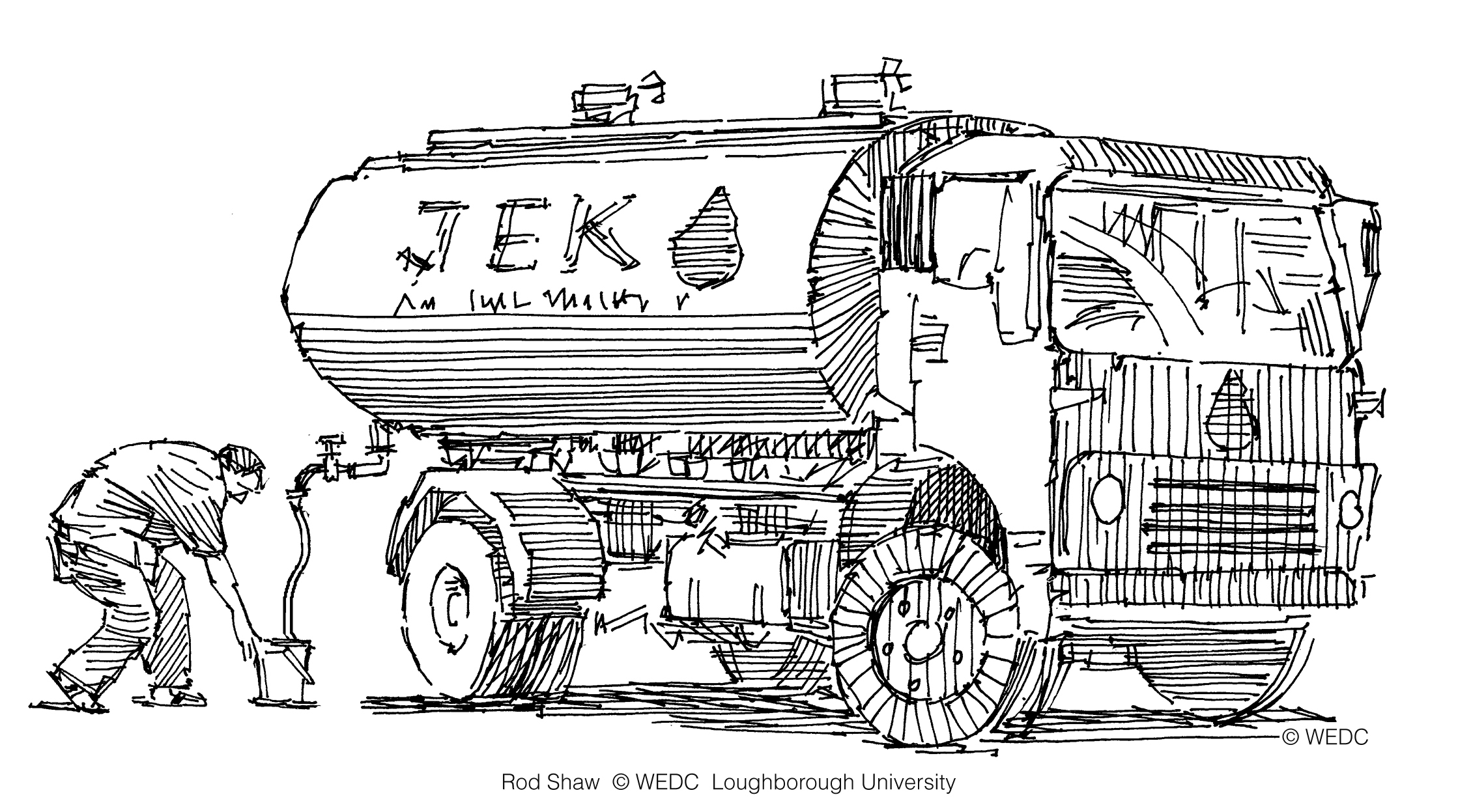
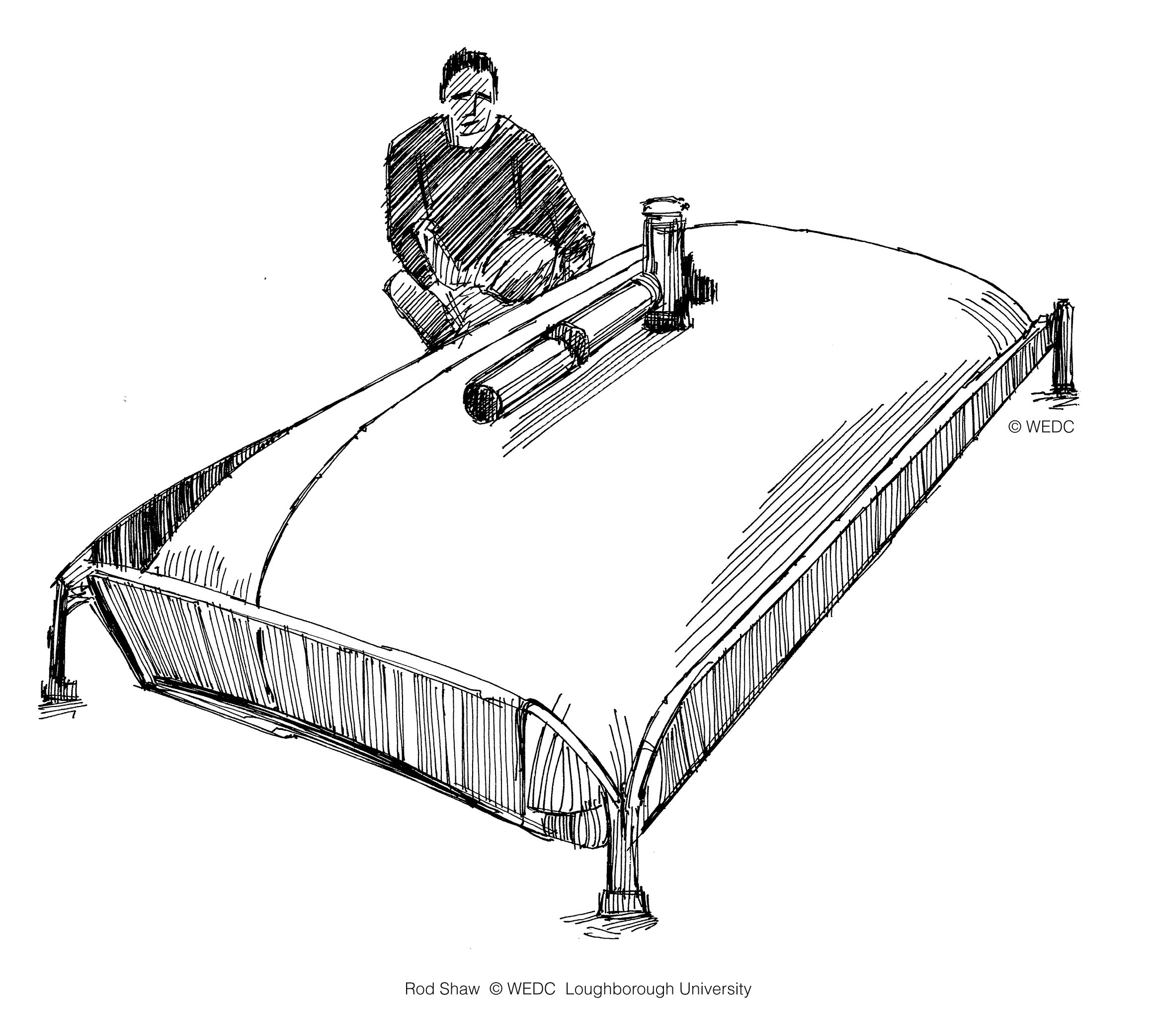
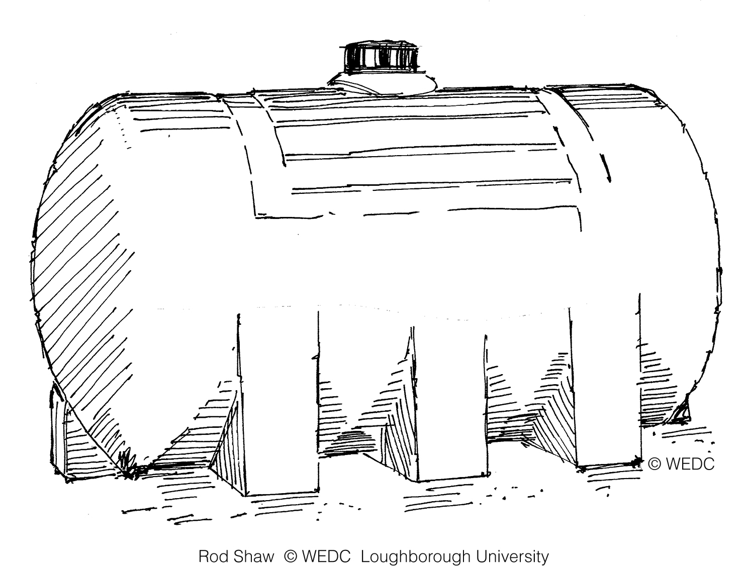
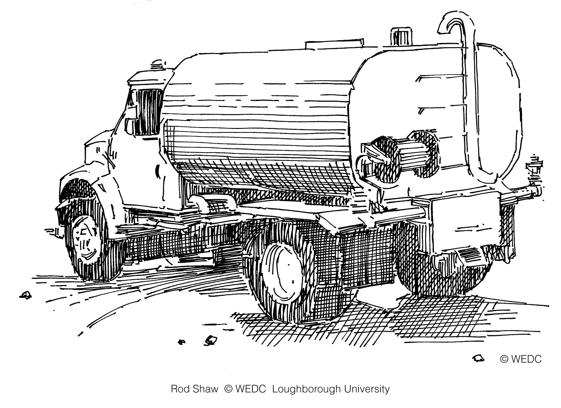
Group meeting around a table | JEK water tanker | Pillow or bladder storage tank | ||

|
|
| ||
Pre-fabricated collapsible water storage tank | Prefabricated well lining | Rainwater catchment frame | ||
|
|
| ||
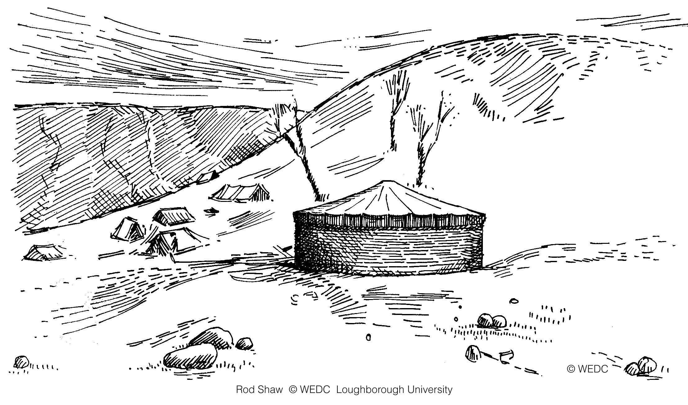
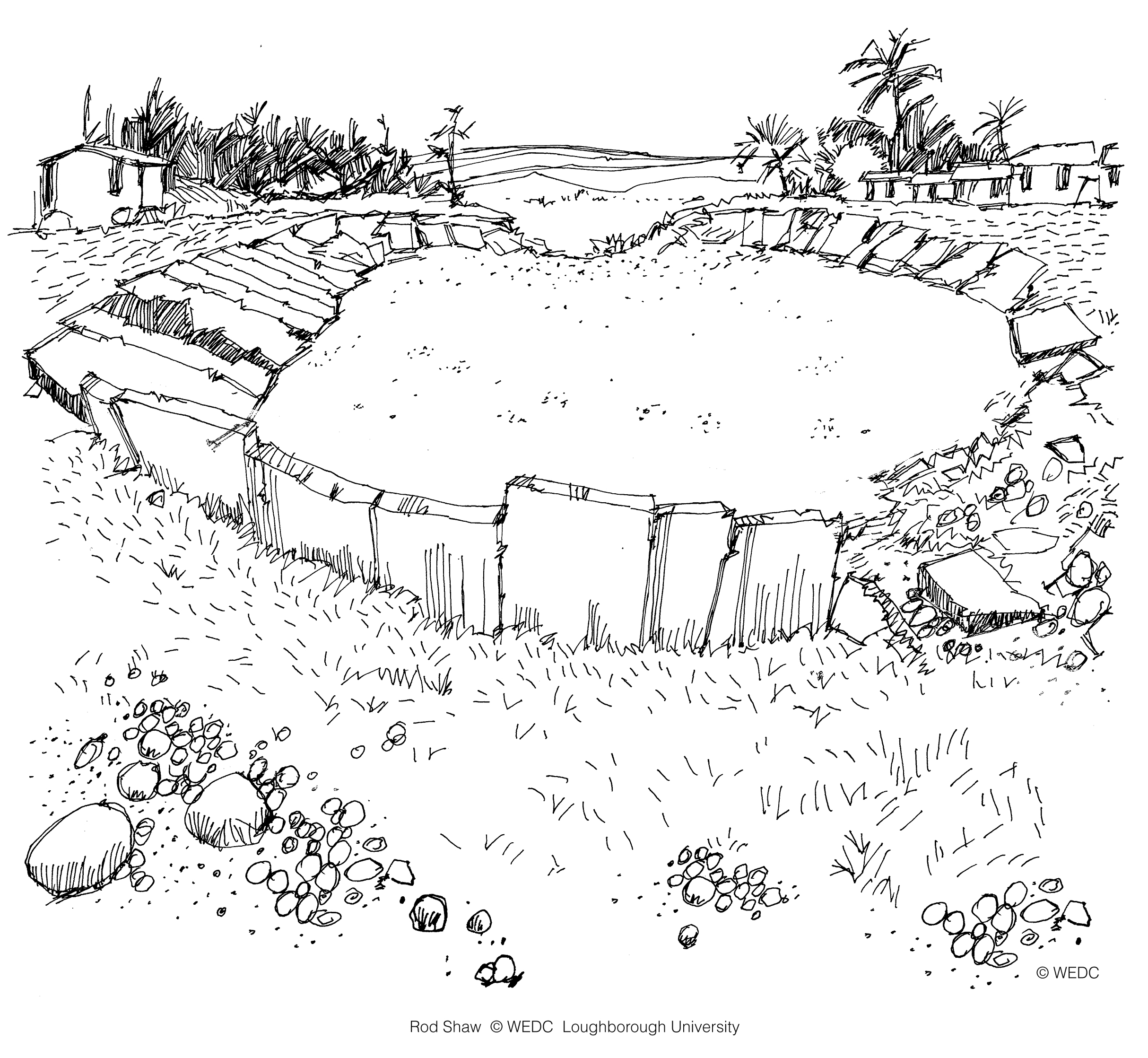
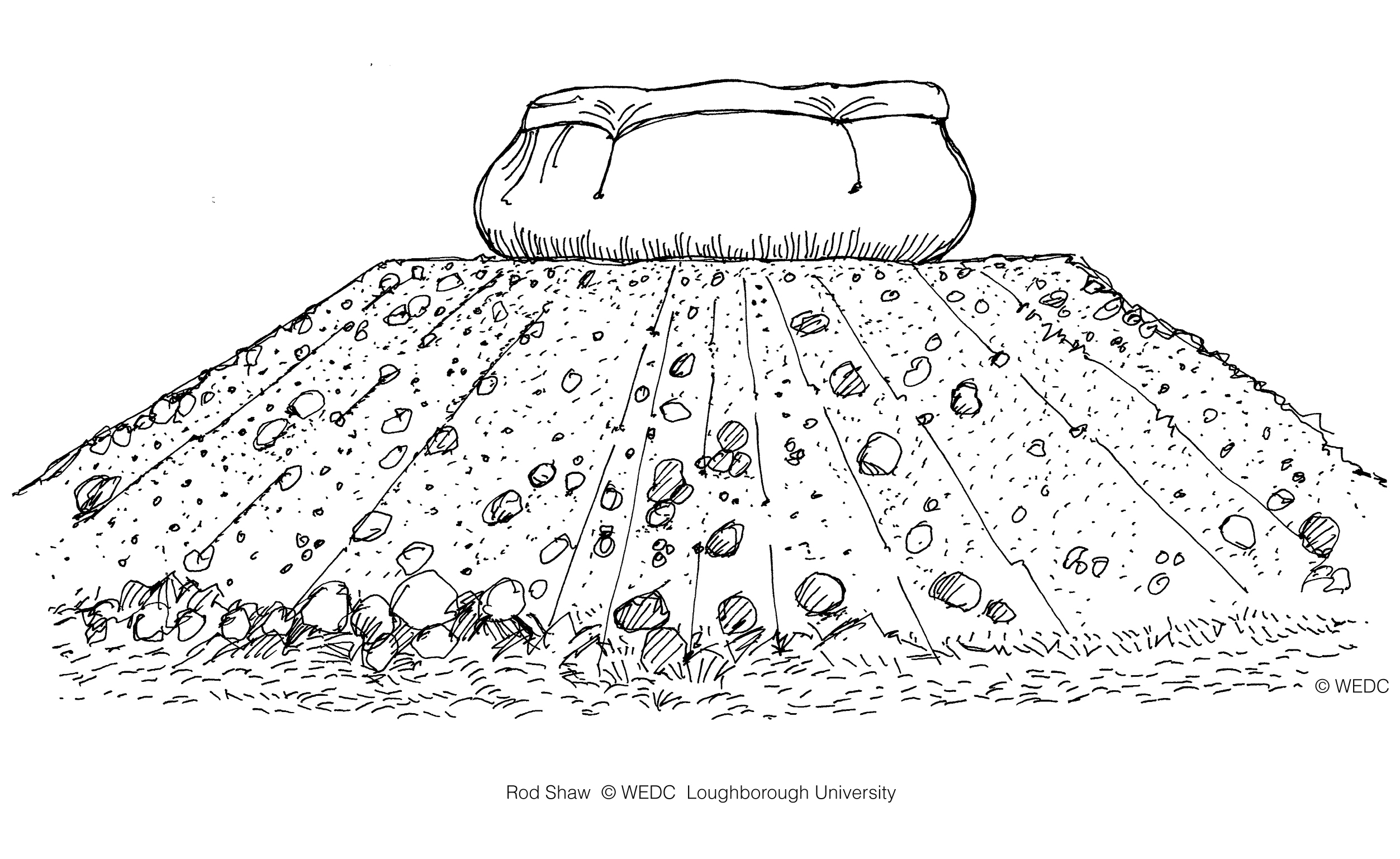
Rigid metal or plastic storage tank | Storage tank damaged by flooding | Storage tank on an artificial mound | ||

|
|
| ||
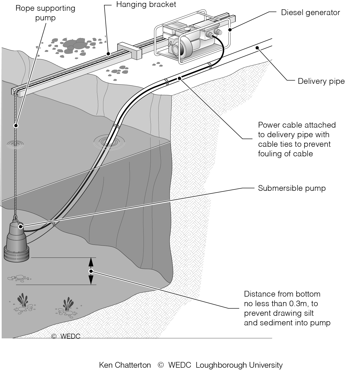
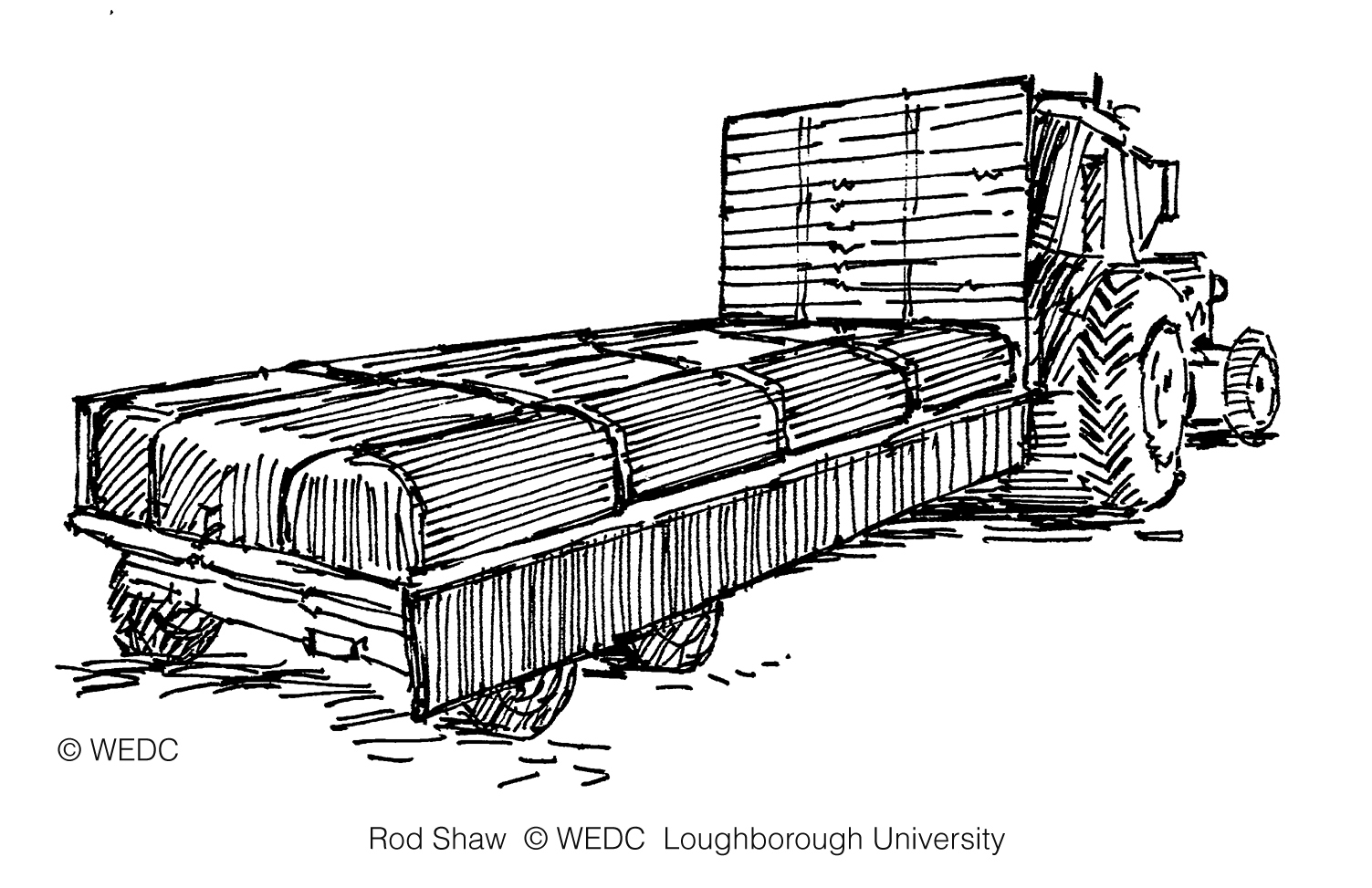
Submersible pump and portable generator v1 | Submersible pump and portable generator v2 | Tractor pulling a bed trailer carrying a bladder tank | ||
|

|
| ||
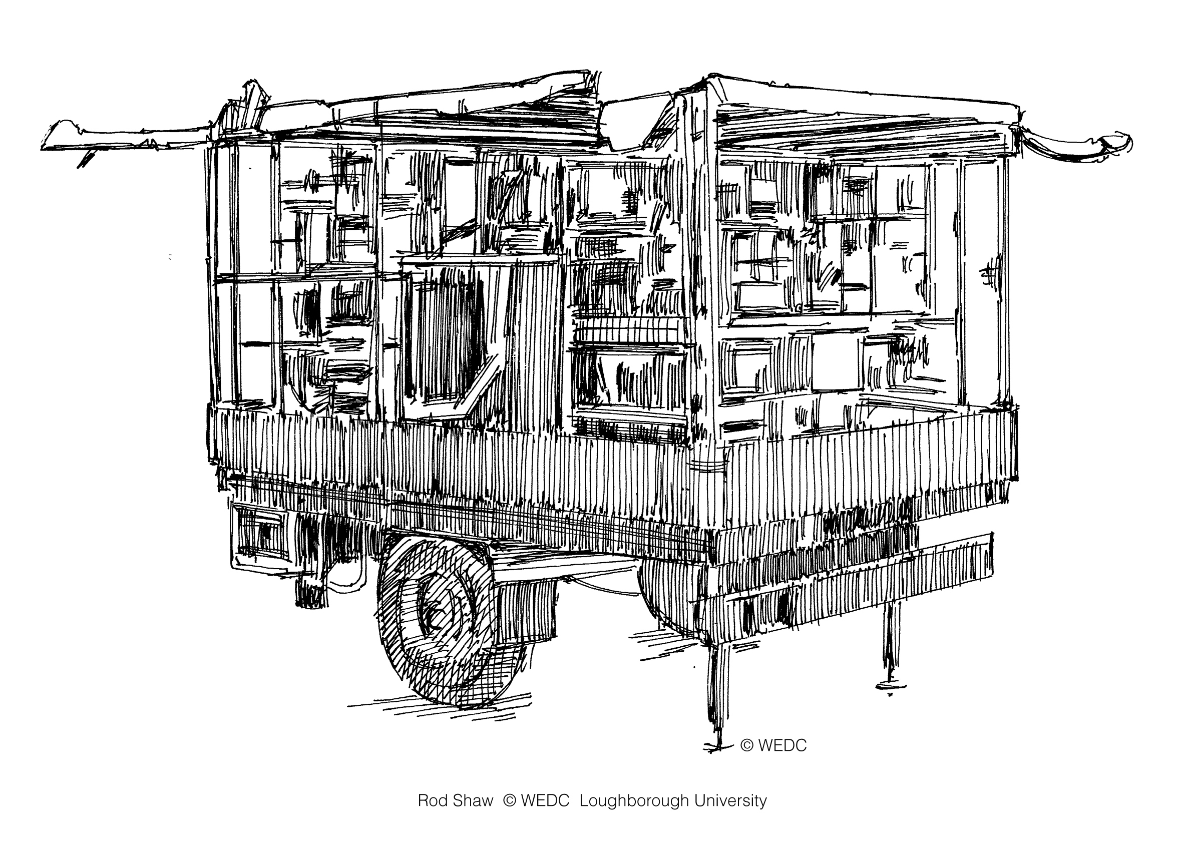
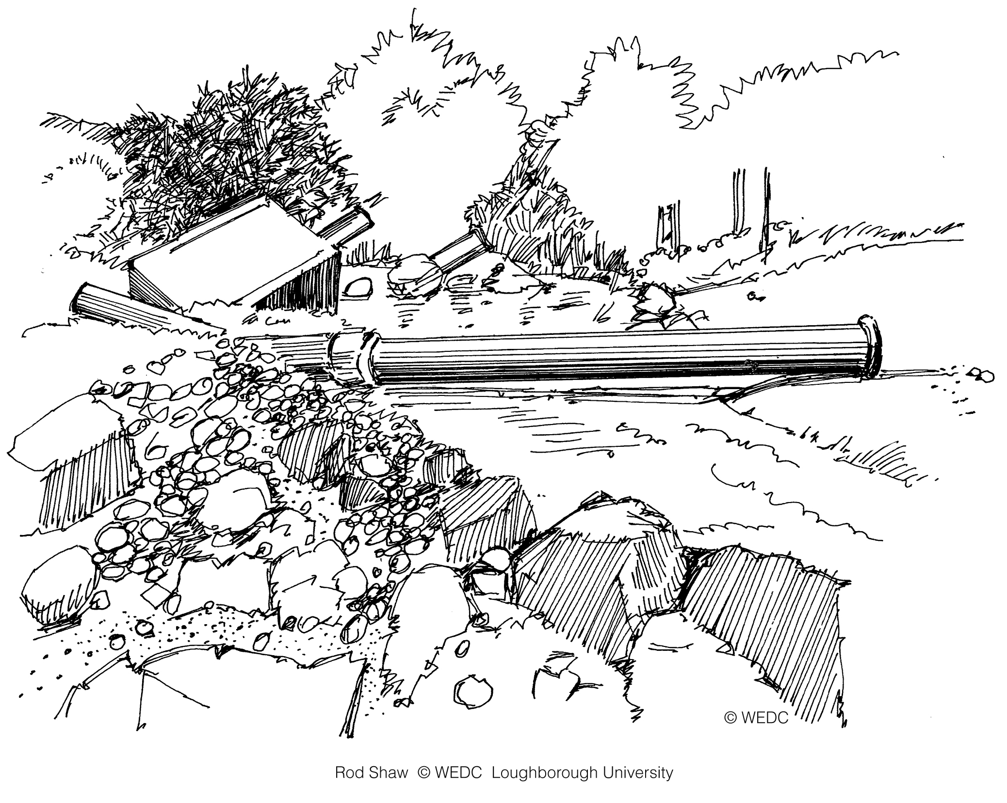
Trailer mounted mobile water treatment plant | Using a motorised pump to increase the pressure in a distribution main | Water supply intake destroyed by floods | ||
|
|
| ||
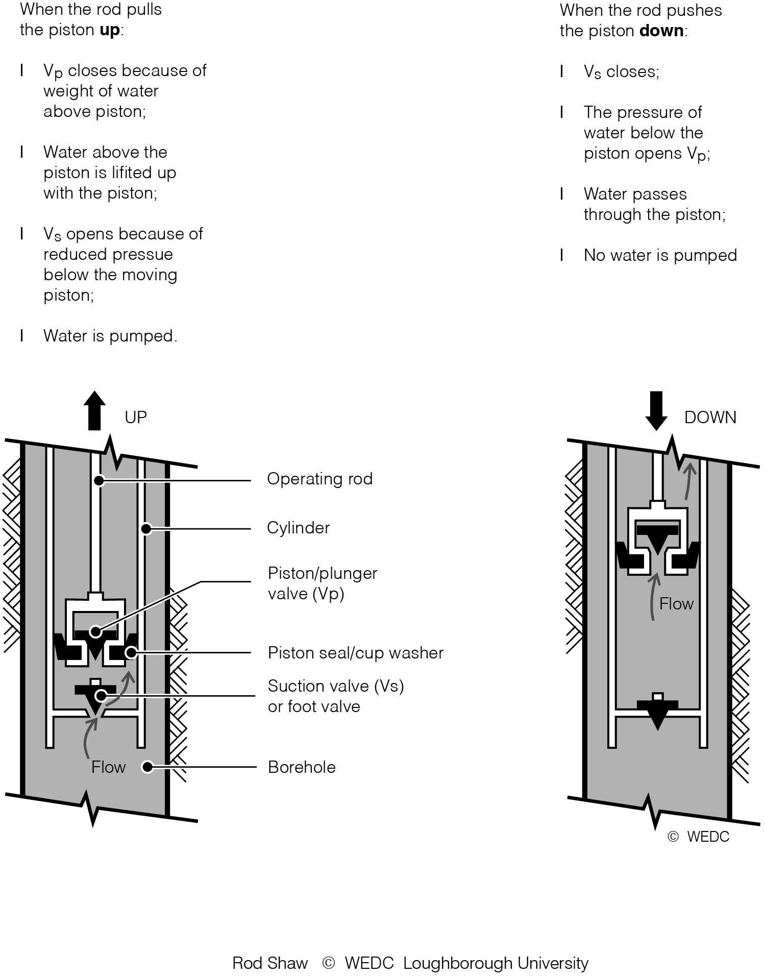
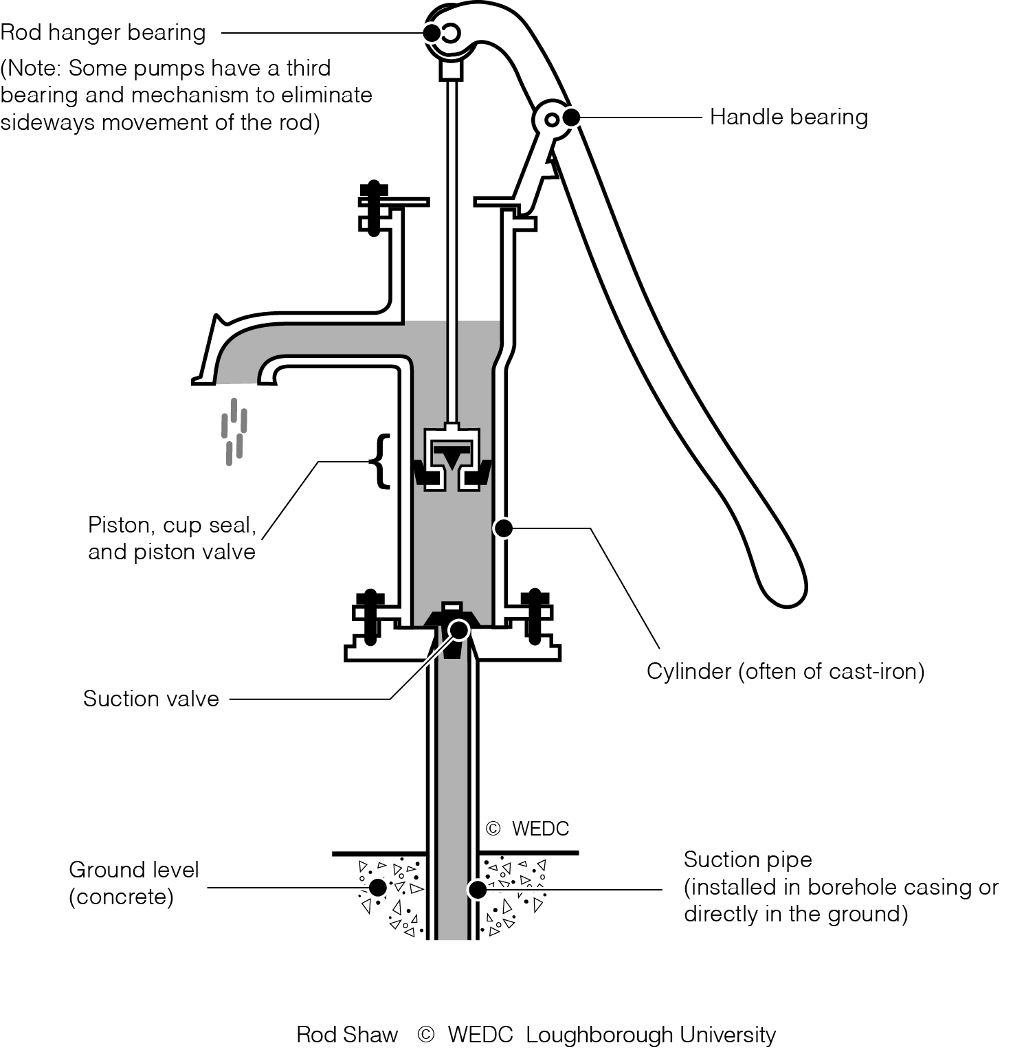
Water tanker | 11-18 Schematic diagram of the working parts of a reciprocating piston hand pump | 11-19 Workings of a suction lift handpump | ||
| ||||
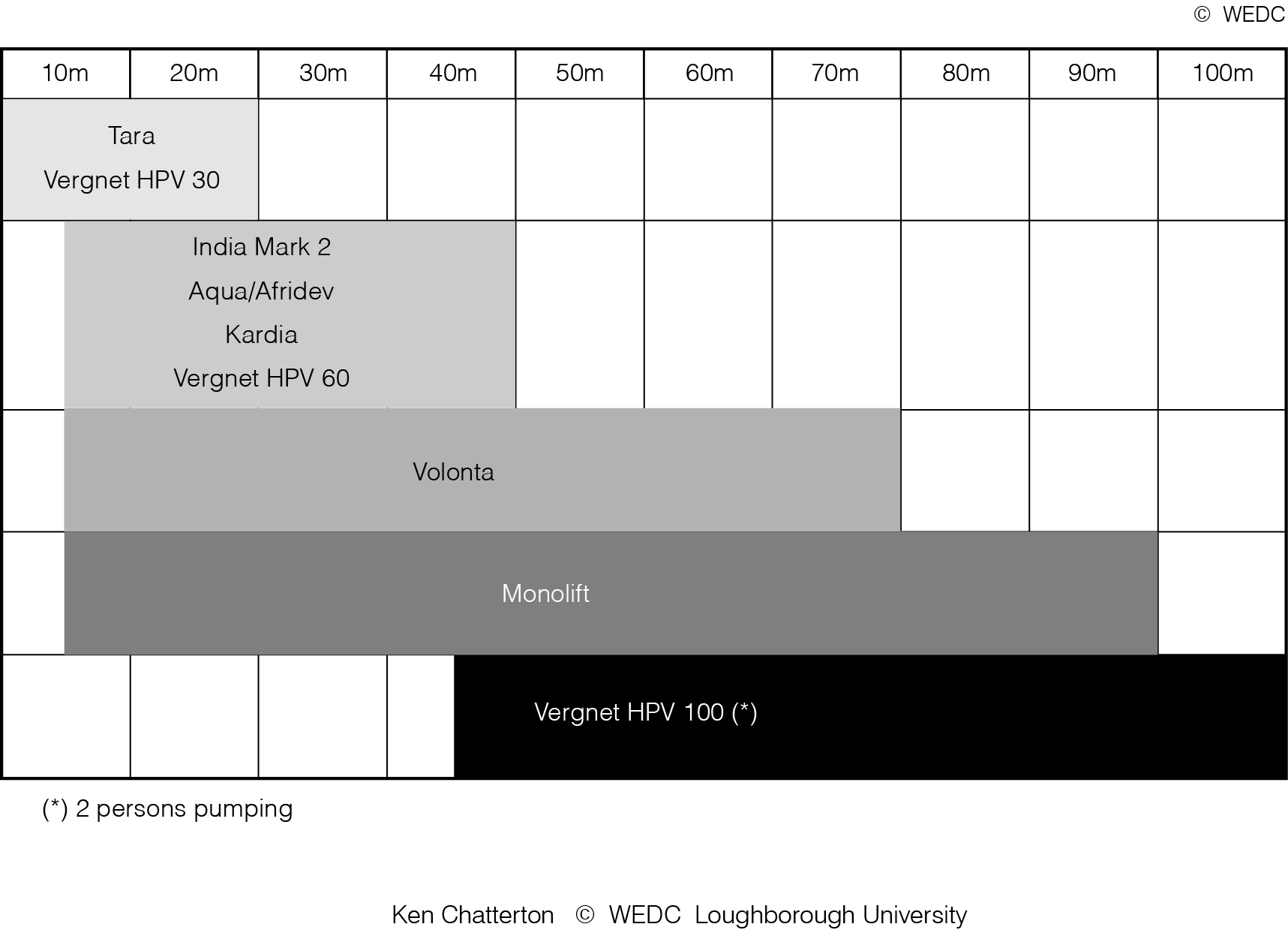
11-20 Normal working range for common handpumps |

© 2026 Loughborough University. All rights reserved.
My WEDC Terms & Conditions | Privacy Policy